Friday, October 16, 2015

Hart Convertible Gondolas: Press "Buy" Now!

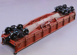
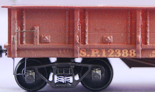
Built-up SP W-50-3 Hart convertible gondola kit.

If you've liked the Southern Pacific W-50-3 Hart convertible gondolas I've been 3d printing and wished you could have one for your layout, today's your lucky day!

I'm now selling the SP Hart gondolas as kits. Price will be $32 for the body, instructions, and decals. You can get either models with the hopper doors open for ballast dumping, or with the hopper doors closed for gondola use or side dumping. You'll need to provide trucks, couplers, wire, end steps, brake wheel, and a bit of styrene strip. See the Dry Creek Models website for more information, or drop me a note at info@drycreekmodels.com.

I'll be sharing some stories of manufacturing these kits over at the Dry Creek Models blog, so keep an eye over there if you're interested in the cars I'm making or for more details about 3d printing. I'll continue to talk about random adventures in 3d printing here, as well as sharing the usual updates on the model railroad and San Jose history.

Wednesday, August 19, 2015

Next 3d Freight Car Model: Southern Pacific's "Battleship" Gondolas

Boy, I've been awfully quiet lately; I'll put at least some of the blame on that 3d printer. Just to show I'm not goofing off, I'll show some of the latest work.

Here's the latest result: Southern Pacific's "Battleship" gondolas. The "battleships" were side-dump ballast cars built around 1902, and they're cool cars from so many different angles.

The Battleships are interesting construction-wise because they're some of the Southern Pacific's early steel freight cars, completely built using steel plate and angles, riveted together. They're sort of like the Eiffel Tower of freight cars in that way - big, metal, and covered in rivets, and they probably impressed the locals at the time for the same reason the Eiffel Tower was impressive. When I saw the plans at the California State Railroad Museum a few weeks back, I found they're just as interesting underneath, with a three foot tall I-beam running down the center of the car, and all sorts of cross-bracing supporting the interior A-frame for the slope sheets.

The cars are also interesting appearance-wise because they look unlike any other freight car. The available photos make the cars look big and boxy, even though they're only 30 feet long - short by modern standards, and even small for my 1930's era. The unusual hinged doors covered each side completely, and the arrangements of hinges catches the eye. Their air-operated mechanism for the side doors are beautifully steampunk with ten foot long operating levers covering the sides.

And finally, the cars were present at the Southern Pacific's greatest battles. The cars were intended to dump fill on each side of a railroad track. Three hundred were bought for the Lucin Cutoff work - Southern Pacific's attempts to tame Utah by running a railroad straight across the Great Salt Lake. They were used in the fill work to block the Colorado River's escaping of its old channel as it tried to fill the Salton Sea. The cars hauled debris away from San Francisco after the Great Earthquake and Fire of 1906. They were used in countless other improvement projects, with some cars lasting into the 1950's in maintenance-of-way service.

These cars were printed on my Form One printer, printed upside down (top to bottom) for easier support during printing. The needed support structure attached along the top rim of the car, and also had individual supports down into the interior. These versions of the model have only been painted with primer and touched up with a bit of putty; I still need to install grab irons, brake gear, and still need to paint and decal the models.

The air-operated mechanism for opening the doors was the touchiest part of the cars to design, and I'm surprised it printed as well as it did. You can see that some of the levers are supported from behind so that the car can be printed in a single piece. I found the lower frame the hardest where shallow angles support the slope sheets that stick out just beyond the edges of the car. The interiors were the fun part because they forced me to fully understand how the car was supported - posts come up from the lower frame to support the top of the car, and a different set of supports braces the door below the hinge point.

Oh, and a pro tip for folks building 3d-printed model railroad models: always take a picture with a coin or X-acto knife. Otherwise, you'll look at your photos and think "wow, that's a lousy model", and then you realize the detail you're complaining about is a literal pinhole.

How Big Was the Heating Oil Tank at J. S. Roberts?

"You don't need to know how many cars could fit on the team track at the San Jose Western Pacific freight depot to build your layout. The answer is "three", by the way."
--Byron Henderson

Not every model railroader is interested in history, but there's enough so that some potential model railroad builders get stuck trying to learn every possible detail about their prototype before they ever start building. Byron's quote highlights that we don't need all those details to have fun modeling.

But his quote also highlights how obsessive some of us can get learning about particular places. I'm guilty of that; to build my model of the Vasona Branch, I've done way more research than I really need. One particular source of my obsession has been the packing house at 740 West San Carlos Street, once occupied by J.S. Roberts in the 1930's, but occupied by Abinante and Nola in the late 1940's. I've written about Abinante and Nola many times in the past, and about working on the scene as it would have looked in the 1930's.

But, hey, how could I model that packing house without knowing everything about it? What about their oil tank used for supplying steam to the dried fruit packing plant. Was it 6,000 gallons and filled by the local oil dealer, or bigger, and supplied by rail?

I can answer that sort of question now. Heck, I can even tell you what that tank looked like. You see, I went off for lunch at Paradiso's Deli on Auzerais St., just behind the former Del Monte cannery. After some tasty ravioli and meatball, I wandered off along the Los Gatos Creek trail for sightseeing, and saw a backhoe digging off on the other side of the railroad tracks.

1902-era redwood heating oil tank being dug up.

What were they digging up? Turns out they did an environmental survey on the property at 740 West San Carlos, and discovered that the old oil tank for the packing house had never been removed. Yesterday, they'd exposed it, and found it still had 9,000 gallons of heating oil in it, and pumped out the thickened oil. Today, they were pulling up the tank to check underneath for spills. Odds are the tank was placed in the ground in 1903 when the packing house was built for Ernst Luehning and his San Jose dried fruit outpost. It was in really good shape for a hundred year old *redwood* tank that had been holding something similar to diesel fuel for all these years. The joints were still tight on the tank, and was little sign of fuel leaking through.

More importantly, the Sanborn map lied; it wasn't a 6,000 gallon tank, but closer to 12,000 gallons - probably just the size to deserve a carload of heating oil a few times a year.

Now, I'm not a stranger to the idea of shoving oil in the ground - when we lived (briefly) on the east coast, we lived in two houses with heating oil; in both cases, we had to remember to call the oil company to dump a thousand gallons of oil in our front yard so we didn't freeze to death. In our last house, we didn't quite trust the landlord to compensate us for oil we left in the tank on moving, so we tried to stretch the tank for the whole season... and ran out just before a huge snowstorm hit. Ugh. After that mistake, I really can't imagine anyone moving out of the packing house without taking those 9,000 gallons with them. But I guess landlords were much nicer in San Jose back then.

If you're ever over to see the model railroad, look over just to the right of the packing house, and with luck I'll have added some piping and vents for a certain 12,000 gallon oil tank that I know occupies exactly that spot on the model railroad.

And if you're one of those folks doing the environmental impact surveys, try aiming a couple hundred feet west. The Zicovich Winery was out there in the 1890's, and with some luck you might find some barrels of wine that survived the Great San Carlos Street Fire of 1899. Much more tasty than half-century old oil.

Photo of tank being dug out of lot at 740 West San Carlos taken by me, August 19, 2015. Thanks to the crew doing the removal for talking with me about the fun of discovering an removing the old tank. Thanks to the crew doing the digging for chatting with the strange obsessive model railroader about their site.

Sunday, July 19, 2015

Research Road Trip: Road Routing Proof, and More Projects

As much as I care about modeling prototype scenes accurately, I also realize I'm using the historical research just to help me figure out what to build as part of a hobby and relaxation. The model isn't meant to be a perfect representation of history; sometimes, I'll build stuff because it's fun (ex: the Goleta gas station sitting on Meridian Road) or because a particular model might not be perfectly accurate, but it still gives the sense of the Santa Clara Valley I'm trying to share.

Back in 2009, I talked about my notebook of location sketches that I used to remember photos of particular locations. I was using my map of Wrights at the time to redo the scenery around there; my big question was how the road went between the Wrights depot and the (still-existing) road bridge. I'd guessed at the time that the road dipped under the railroad bridge. I wasn't sure if it was perfect, but (1) it was plausible, (2) I wanted to improve the scene, and (3) I wasn't going to get better information any time soon. I rebuilt the scene anyway, and it's a nice scene.

1911 Wrights map

Six years later, I know the answer about the road for certain.

I did another day trip up to Sacramento last week. It's a bit of a long slog, but I enjoy getting the chance to search through old archives, look at original documents, and get a better understanding for how things had been. It can be boring work, but the occasional revelations and surprises make for a satisfying day.

I had a bunch of other goals for that visit, but found some time to look for materials on some of the stations along the Los Gatos brach. One of the stops was at the California State Archives. Most of their archives can be dry - corporate records, transcripts from California Railroad Commission cases, etc. They've also got microfilms of some railroads drawings from the early 20th century, probably collected as part of some state law at the time. I poked around in several of the maps along the Vasona branch - Foyle (location of the brickworks on Fruitvale Ave.), Vasona, and Wrights. One of the finds was particularly cool - the April, 1911 map of Wrights in their collection shows "Depot Road" passing under the bridge, in pretty much the same way I guessed. Woohoo!

Cover of Wrights bridge rebuilding brochure

Plan of rebuild of 6th crossing of Los Gatos Creek near Wrights

This was just one of many discoveries that day. The California State Railroad Museum had a handful of other docs to highlight the details - the 1914 equivalent of a PowerPoint presentation talking about a rebuild of the bridge crossing Los Gatos Creek (with shape of piers and cost) also showed where the bridge crossed the road. (Congrats to the Southern Pacific; their intern from 1916 did a great job on the brochure!) A 1938-era map showed the road passing under the bridge, even as every other building in the vicinity had been removed. A 1938 map showed the Wright station removed.

It's great knowing that I got that detail right. Some might ask "why did you build it if you weren't certain about the arrangement?" To be honest, my guess about its location wasn't too far off the mark. Although I could have held off on modeling Wright until I got that detail right, I'm really glad I didn't wait six years but instead built something that was mostly correct. It's more fun to have an operating layout with fun scenery than to have something that's 100% accurate.

The maps also showed a bunch of interesting details that are worth adding. Several maps showed a freight house on the "Sunset Park" spur just before the tunnel; the 1910-era maps also showed packing houses that (sadly) aren't visible in later years. All the maps show wooden "bulkheads" along the creek keeping the hillsides from eroding into the creek.

The last map also highlights some cute little details that never made it into photos. About a hundred yards down the track, the map shows a "shed made of bridge stringers", and an old narrow gauge car body on blocks next to the tracks, joined to a small frame building. (An annotation mentions the buildings were sold to "W. E. Hughes".) Those buildings would be neat details to add to the layout. The photos of the Wrights bridge also points out my trestle-style bridge isn't quite correct; to be accurate, I really need a 50' steel girder bridge "from Santa Clara River (Montalvo bridge)", along with some large concrete piers to hold it up, and some timber trestle on either end.

And on top of all that, the maps highlight little bits of history that aren't relevant for modeling, but do highlight the place I'm modeling, and life in the Santa Cruz Mountains at the beginning of the last century. The 1911 map shows that one of the packing houses was used as "Dance Hall and Packing House", highlighting how buildings shared multiple purposes in rural towns.

The 1911 map also contains an unnatural fascination in running water for the town:

Note: All properties shown excepting that marked Nick Bowden are owned by Matty. Cottages 1, 2, 3, 4 & 11 are occupied only in summer. Each has 1 3/4" faucet. Cottages 6, 7, 8, & 9 are occupied only in summer. They get water from the one faucet shown. The saloon, hotel, & livery stables are rented and run by B. Borrella. The saloon has 5 3/4" faucet shown & 1 toilet. The hotel 7 3/4" faucets & 1 toilet, the livery stable 2 3/4" faucets and 1 1 1/2" faucet. The blacksmith shop has 1 3/4" faucet. Cottages 5 & 10 are occupied permanently, each has 1 3/4" faucet. The grocery store is rented & run by Chas Squires, & has "1-1" & 1- 3/4" faucet. The chinese store has 1 3/4" faucet. The dance hall has 1 3/4" faucet. The Earl Fruit Co. packing house has 1 3/4" faucet. Nick Bowden's place has 1-3/4" faucet.

That accounting of faucets might say something about whether water would be available for other development; one of the later maps at CSRM showed that the railroad water tank was filled from small dams along some of the ravines north of town, which couldn't have supplied much water, and must have been dry during summer. If I had a thirsty locomotive in the middle of summer, I'd be unwilling to trust there was any water in that tank.

None of that matters for building the model (except for the notes about both Earl Fruit and the freight house existing), but it does hint at Wrights being a quiet rural village that would have been near-empty during the winter.

Excerpts from 1911 Wrights Station map from the California State Archives - ask for the "Aperture" cards, and check the card catalog in the research room to see what's available. The excerpts from the Southern Pacific "S.P.C. Bridge Renewal" brochure from the California State Railroad Museum's archive. They've got a similar brochure for the next bridge downhill towards Los Gatos that I haven't seen. Great thanks to the research staff at both libraries for their help!

Sunday, July 12, 2015

3d Printing: New Designs are Hard, Tweaking Designs Is Too Easy

As I’ve been showing off the 3d-printed Hart gondolas, one of the common questions I’ve gotten is “how long does it take to make the design? Could you just scan some commercial model?”

That question goes a lot to the challenge of 3d printing. Although the technology seems magical (“press a button and a freight car comes out”), there’s a huge amount of work to design a model. Having an existing thing - whether a real car or an existing model - doesn’t help. You’d need to get a scan, clean up any imperfections, add detail in the places that didn’t scan well, adjust the design to either exaggerate detail that would get lost when printing at your scale, and hide detail that won't print well.

For example, rivets smaller than about 1.5" diameter don't print well, so I usually do both rivets and bolt heads as 1.5" diameter, 1" tall cylinders. Models with a board floor need gaps drawn in to show off the boards, or require each board to be at a different height to be visible; either choice affects spacing, and how the floor attaches to other parts of the model. Detail that needs to be painted on, such as a metal strap, might need to be raised up so it can be hit with a paint brush. Metal structural parts, such as angle iron, needs to be thickened - 1/4" plate used for stiffening a railroad car would be 3/1000 inch thick - perfectly solid on the prototype, but impossibly flimsy on a model. Changed dimensions might snowball into affecting other parts of the design. Making decisions about how the design should be tweaked requires judgements about what can print reliably, and what detail is essential or unimportant for a model. For lack of a better term, it requires a bit of "art". (Folks making plastic kits have to worry about all these details all the time; check out a plastic boxcar to see the mold maker's choices.)

Fixing an existing scanned design to fix details and make the judgement calls about scale is a ton of work. In many cases, it might be easier to start with a rough idea of what you want to build, and then design from scratch in 3d, just as if you were making technical drawings on paper.

Making a 3d model of a freight car isn’t easy, either. For the three cars I’ve built (the CS-35a flat car, the F-50-4 flat car, and the Hart gondola), I built the models mostly based on photos. I grabbed my copy of Tony Thompson’s “Southern Pacific Freight Cars” book off the shelf, started with any drawings he included, then started guesstimating from the photos. For the CS-35a and F-50-4, Tony included very tiny copies of the original drawings; with these and a good magnifying glass, I could get a decent idea about measurements. With the photos in the book, I could identify some of the details, such as the shape of the stake pockets or guess at dimensions I couldn’t read.

End elevation from Hart gondola plan.

Making the 3d Model from Photos: With the Hart gondola, I had more of a struggle; the Freight Cars book didn’t have any drawings. Tony did include minimal information on car length from an old car description, but other than that, I was on my own. Multiple times, I printed a model, then looked at the photo to compare scale and look for details I missed. The result was pretty good - certainly good enough for my model railroad - but I knew there were mistakes.

So fast forward a couple months, and I’ve decided to try doing another 3d model - this time the Southern Pacific’s “battleship” side dump ballast cars, built in 1902. These cars were critical for the early SP, helping to create the fill across the Great Salt Lake, hauling away the debris from the 1906 San Francisco earthquake and fire, and plugging the Colorado breach to stop the flooding of the Salton Sea. These were huge boxy, coarse steel freight cars that, in every photo, were dumping immeasurable amounts of rock to stop a river or cover a hillside.

For the Battleships, the book only had eight photos, mostly side views. With those, I could get the rough outward appearance. However, the insides weren't visible in any of the photos. I needed to understand how the inside of the hopper was shaped - these had a triangular shapes interior to slide rock to the outside, and those insides would be very visible on the completed model. The photos also hinted that the car was mostly hollow, with support structures underneath holding up that hopper bay. 3d printing promised to get that internal structure just right, so I really wanted to get that non-visible structure correct.

It was time to go to extraordinary lengths.

So last week, I headed up to Sacramento and the California State Railroad Museum to search for more information. The CSRM managed to save many of the plans and blueprints from the Southern Pacific, so for details on obscure, century-old railroad cars, it’s the best hope for information.

Finding the Original Hart Plans: I went up looking for three bits of information. First, when I’d shown off the Hart cars to Tony Thompson last month, he hinted that the cars had been rebuilt in the late ‘teens. “After the rebuild, the cars were two boards higher.” I wanted to find plans for the rebuild so I could make an accurate modern version of the cars. Second, I wanted to find blueprints for the Battleship cars; although I’d been able to print a rough model, I couldn’t see how the frame of the car was built, and wanted to get that right. Finally, I wanted to poke around for more information on San Jose and the canneries.

I wasn’t so lucky with the Battleships and the rebuilt cars; plans for both are stored off-site, and need a week’s notice. (Pro tip: WS and McC call numbers on plans imply they're stored off-site in West Sacramento and McClelland Air Force Base.) However, the staff did find a beautiful set of plans for the original Hart gondolas (last revision, 1918), all on a 30x60 piece of vellum. The drawing is a beauty - some draftsman spent a huge amount of time getting the it perfect, even sketching in the wood grain on some of the posts.

And now I’d put myself in an awkward situation. I already had spent a lot of time on that original model. I’d guess I’ve spent 40-50 hours on it, both in getting the rough design done, and fine-tuning it for printing. And now I had accurate plans, and knew all my mistakes. If I’d scratch built my ten gons, I might have stopped and said “good enough.” If I hadn’t thought that someone else might be interested in the gons, I might have stopped too. But now I knew I had an imprecise model. Worse, I had the ability to change that model.

Detail, Hart gondola door. Note how U bolts and angle iron were used to fabricate the hinges, and note the detail on the door latch that I never could see accurately in the photos.

I sat there for about 20 minutes just looking over the details. Ah, the straps hinging the side doors were actually angle iron, not steel strap. The trusses underneath the car were much deeper (3’) than I thought, and fabricated from larger iron angles. The metal aprons that could be flipped across car gaps only existed on the brake end of the car. I had the length and door spacing slightly wrong. I hadn’t quite understood the mechanism for opening the bottom dump doors.

If you look at the snippet from the drawing, you can see just how much detail is there. There are the revisions about where the handrails go on the car ends. You can see the “v” notch cut into the sides to hold the hinged-up doors. You can identify how metal rods wrapped around each post, then held the posts firm against the frame and truss. You can even see the metal plate joining the side frame and truss, and see the I beam going through the hopper area only joined to the inside of the frames - details I could sort of see in the photo, but now really understand.

Now, it's also worth noting that my original cars weren't that bad. The models I designed were eye-catching and reasonably accurate. The general proportions of the car were good. They're still worlds better than either of the two 1960's plastic or metal kits would have been. Many of the incorrect details I spotted were insanely minor - cases of replacing a metal plate and bolt with a pair of bolts-and-washers, or placing the removable ends just outside of the line of side posts. But I know there are inaccuracies.

So now I’m redoing the Hart gondola - stretching parts correctly, adding details that I hadn’t known about, and hopefully adding some parts of the mechanism. And once that’s done, it’s time to print, paint, and decal some accurate Hart gondolas

I’m still planning on dealing with the “rebuilt” Hart gondolas and the Battleships. I’m going up next week to see those plans. I suspect I’ll be spending a lot of time in front of the computer over the next couple weeks as I pore over some draftsman's really fine work. Stay tuned for more photos of 3d printed freight cars!

Snippets of drawings from Southern Pacific / Union Pacific C-1652 plan, used on SP’s class W-50-3. Last revision April 19, 1918. Original in California State Railroad Museum.

Friday, June 26, 2015

Don't Trust Robert's Advice on 3D Printed Buildings

In the past, I've declared that 3d printing isn't great for buildings. Most buildings are easy to make using sheet styrene or sheet wood - I can probably build them faster than I could draw them on the computer. I only need one copy of a particular building, so the ability to print multiple copies isn't so interesting. Buildings tend to be large; they're either slow to print, or won't fit at all in the 3d printer. I'll admit I've used the 3d printer to make details (such as the architectural details for the Market Street station, or the freight doors I borrowed from the Guggenhime packing house. But buildings? Not worth the trouble.

Well, actually, sometimes the 3d printer can help with buildings, and two recent projects highlight when the printer might come in handy.

J. S. Roberts and clerestory windows Early 20th century buildings often used clerestory windows - raised sections of roof with small windows - as a way to bring light into the center of a building. We usually think of this with sawtooth roof factories, but you'd also see this in frame structures. The J. S. Roberts packing house off San Carlos Street got light into the fruit sorting area on the third floor with a raised roof and some small windows, all above the barn-like building's normal roof line.

J.S. Roberts clerestory windows

Clerestory windows like this are a pain to scratchbuild. There's not a lot of good, tiny window castings if you're trying to model a strip of two foot high windows. Because the clerestory roof is often only raised a couple feet, building the walls around the window can be difficult. If the clerestory is on a peaked roof, then I've also got to cut the ends to match the roof slope precisely. The last time I did a model like this, I used some 3d printed blocks to form the clerestory section, but still had to cut the lapped siding sheet to fit. For that model (the Earl Fruit Company packing house on Ryland St.), I wasn't completely happy with the overall clerestory look (too few windows, clerestory section too tall), but I decided it would do.

When I completed the main section of the J.S. Roberts packing house, I knew I needed to make another clerestory roof to finish the project. However, the 1930's photos I'd seen showed a very short space between the two roofs. I couldn't think of any commercial windows that would work, and I knew the whole assembly would be tedious to build.

Clerestory 3d model

Roof and access hatch

Instead, I cheated - I sketched the whole clerestory roof - siding, windows and all - as a single piece. I didn't have to worry about cutting the angles against the roof (as long as I measured the angle correctly.) I could size the windows to exactly match the space. I did have to draw out the location of *every single board* for the siding - tedious, but doable on this relatively small model. The result was too big for the printer, so I split it in two, printed two copies, and glued the pieces together to make a completed clerestory assembly. After painting and attaching corrugated siding for a roof, I was done. The windows, although solid, got some black gloss paint to make it look like there really was glass in those panes. The result was just right - a roofline that matches the prototype and I didnt have to cut any fussy angles.

In fact, I was happy enough with the result that I did another 3d print for the access hatch on the roof. Again, by 3d printing it, I didn't have to worry about cutting the correct angle into plastic siding, and didn't have to worry about fabricating a tiny box perfectly square.

Campbell passenger shelter for the Peninsular Railway

The Sourisseau Academy, one of the local history organizations in San Jose, posted a picture recently of downtown Campbell in the 1920's. The photo, showing the area around the railroad tracks and Campbell Ave., reminded me that the former Peninsular Railway, an interurban line, used to go from downtown San Jose to downtown Los Gatos via Campbell. The tracks cut through the new suburbs of Willow Glen and turned here and there through orchards. Just before the tracks reached downtown Cambpbell, they curved off Campbell Ave. and onto Railway Ave to pass next to the old S.P. depot. The Sourisseau's photo shows Campbell Ave. at Railway Ave. - the curve of the interurban tracks, the overgrown mess of the SP's former garden at the intersection, and a small passenger shelter at the intersection which must have been handy both in the rain and on really hot days in summer. (The photo is visible in the Sourisseau February 2015 video, showing the interurban tracks turning south onto Railway Ave.)

Now, the passenger shelter wasn't much - a bench for a couple people, simple siding, and some minor architectural details to please the town burghers. It's also exactly the sort of model that's easy to make in styrene with a couple hours work. I was still curious whether I could make one in 3d, and did some quick sketches.

Applying the siding was the annoying part; rather than just pulling some lapped siding sheet out of a drawer, I had to draw each board: correct spacing, correct overlap at the bottom, etc. The rest was pretty trivial, with the hardest part being the choice of how to print the model. (I chose to print it upside down, with the roof having the bad surface where the model attached to the 3d printer.) Some filing, and some Campbell shingles completed the model. It's not much, but it showed me that I could create small structures quickly. More importantly, I got to play around a bit with the design and experiment with the decorative eave ends. For my layout, 3d printing the shelter is a bit of overkill, but if I needed three or four, it might have been a suitable project for 3d printing.

I still think 3d printing isn't particularly useful for 3d structure models, but these two projects reminded me that 3d printing could still be handy either for work that would be challenging to do by hand, or where I wanted to experiment with details or shapes.

Showing off the 3d Models

I’ve obviously been writing lots about the 3d printed freight cars over the last several months. Apart from showing them to the local model railroad lunch group, I’ve had few chances to show them off in person, show off what 3d printing can do, and share models of otherwise unavailable freight cars.

Last weekend, I went off to the Bay Area Prototype Modelers meet. BAPM is a yearly get-together for sharing models and discussing techniques. BAPM is arranged as show-and-tell; they provide tables, you put down models. Unlike NMRA meets, there’s no contests or judging, no explicit demands for lengthy write-ups describing the prototype - just modelers coming together to share what they’ve been doing. BAPM isn’t unique; there are prototype meets like this elsewhere in the U.S., giving modelers a chance to share. The meets also tend to attract folks interested in specific prototypes, and in modern (1980 and later) models. (See BAPM’s photos from the meet, or read Tony Thompson’s review of the event.)

This sounded like a great crowd to see the freight cars - even if my models aren’t perfect, I suspected folks would be interested in using 3d printing for making specific prototypes. So I hauled a bunch of my freight cars off to Richmond, spread the cars out with a bit of information on how they were made, and had some good conversations.

I went in with a bit of an agenda - the same one I’ve shared here often enough. I wanted to show that a home 3d printer (ok, a pricey home 3d printer) could make models that were approaching the quality of injection molded kits. I wanted to highlight that the technology worked really well for making lots of cars, both because printing a new car was easy, and because I’d end up with lots of “good enough” test prints as I was working on my design. I wanted to show that designing the 3d model was tedious, but possible for folks who were novices at making CAD drawings. I wanted to stress the race between having enough models, and finally getting the design with all the detail I want.

Folks heard that message loud and clear. Harry Wong, one of the organizers, walked up early in the day, and asked “which of the cars was 3d printed”? I waved at all twenty cars laid out on the table. “All of them.” (Pro tip: when showing off 3d printed models, always bring a whole bunch of models to stress that you can make these at will.) Tony Thompson, who wrote the SP freight cars books I used for source material, loved seeing SP prototypes that weren’t available commercially.

I also shared how the 3d printer made it easy to make all the little parts for set dressing - lug boxes, drying flats, piles of sacked prunes. Those parts might not be cheaper than the commercial ones, but it’s nice to be able to make new ones whenever I’m in a set dressing mood.

I also broke one of the prime directives of BAPM. In violation of all the “don’t touch the models” signs, I brought a handful of 3d printed parts for people to touch and examine so folks could get a real feel for 3d printing. (I explicitly had an area on my display to hold the “ok to touch models”, and marked them all so it was obvious what was touchable.) A couple folks noticed the slight warp I’ll get in some of the flat cars (sometimes fixable with careful drying in the sun, sometimes not). Others could feel that the 3d printed cars could be robust enough for operations, or get a sense for the level of details on the models.

Several others asked about what it took to make a 3d model, and whether their particular model could be printed easily, either at Shapeways or on the Form One. One modeler scratchbuilding wind turbine blade loads for flatcars asked about 3d printing some of the odd-shaped mounting hardware that the real railroads use to hold the windmill blades. His particular pieces were perfect for 3d printing - small, slightly odd shapes, with enough bolts and other details to make for an interesting model. Some folks were asking about boxcars; I mentioned my one try at a boxcar and that the 3d printer didn’t do perfectly flat surfaces as well as styrene sheet.

Meanwhile, I also got to see some great models. Along with lots of traditional modeling, I saw three or four other folks building with Shapeways. Jason Hill of Owl Mountain Models had a Shapeways master for the Southern Pacific F-50-4 flat car he intends to make as an injection molded kit. (I spent a good ten minutes comparing my model and his to see what detail I left off; Jason's crawled all over the similar Union Pacific flat car at the Orange Empire Railroad Museum, so he's matched the prototype much better than me.) Other folks were using Shapeways to make specific boxcar doors that weren’t available on production models. There were also a ton of great, traditional models; Jesus Pena showed off the huge fleet of UPS trailers he’s been building for his Free-mo Richmond intermodal yard - at least forty trailers, with plans to double that number for realism.

BAPM is definitely a great meet, and worth attending; it also got me fired up to do the next set of refinements on my models. Next year, BAPM will again be in Richmond on Saturday, June 18, 2016. I’m hoping I’ll have some new models to show off there!

Saturday, February 14, 2015

Movie Night XXII: Million Dollar Dirt

15 years ago, the last prunes were harvested by the Lesters on the IBM Santa Teresa property. Eleven years ago, Olsen Cherries finally replaced their orchards with apartments and retail. Million Dollar Dirt interviews some of the last farmers in the valley, and talks about the change from Valley of Heart's Delight to Silicon Valley. If you know Silicon Valley, you've probably heard the stories, but the movie is a nice chance to hear from the last generations of each family who did farming.

Sunday, February 8, 2015

You Don't Need To Know...

As Byron might say, "You don't need to know exactly what the three required after-market modifications for Ford Model Ts were..." But if you're modeling railroads at the dawn of the automobile age, you might still want to learn.

E. B. White ("Charlotte's Web") noticed that the 1936 Sears Roebuck catalog had lost its section of Ford Model T modifications and repair parts. His goodbye note talked through what made the Model T both good and bad: the parts that everyone bought, straight off. The repairs you were sure to make. The expectation of patching tires, or learning how to crank the car.

Read the full article over at the New Yorker magazine website.

Sunday, February 1, 2015

The Dirty Secret of Printing Freight Cars

BTW, in case you're keeping track, the Hart convertible gondolas were the fourth kind of freight car I printed on the Form One. I've put together a list of all the 3d printed cars I've made, and mention some brief details about each.

With the Hart convertible gondolas, I've finally learned the dirty secret of 3d printing.

Now, if you scratch build a model, it's really easy to make one. You build it slowly; if you get stuck or if something doesn't work, you scrape off the part that isn't working and remake it. Eventually you've got a very nice model. You've also spent a fair amount of time to get to that point. You might be unwilling to make a second, or third, or fourth car because, hey, that would be boring. Making cars only as long as they're fun is fine if you only need one of a particular car, but not so good if you really need a dozen identical cars.

Now, if you were designing an injection-molded freight car, you're definitely aiming at production. You're making either thousands of models for yourself or for others. You'll put a lot of thought into the design because cutting those molds is time-consuming and expensive.

With 3d printing or resin casting, you're in the middle. You're making a small number of items, but you're having to figure out what to make. 3d printing make it easy to sketch up a first model, print it, and iterate. And as a result, you end up with a mighty large scrap box containing all the rejected pieces. Some might be fit only to give you a lesson about things not to do. Other rejected models might be great for a "wreck" at the bottom of a canyon. and some of the rejects aren't so bad...

And now you're in a race. Each time you make a test print, you've made a model that might almost be good enough to use on your layout. You've got some maximum number of models you can probably use on your layout. You've also got ideas on how to tweak each design so that it's closer to perfect and might be useful to other people. So the question is: how fast will you get to "good enough" models and lose interest in printing additional models?

I'm up to twelve or thirteen Hart gondolas at this point, and that's an awful lot for my layout that can't handle more than a hundred freight cars. I've got four cars modeling the gondolas with the bottom doors shut; they look pretty good, but the side sills are too short and won't fit the 7" lettering for reporting marks. So I'm caught - do I use these cars even though they're not quite right, or do I print another four or five cars to get perfection?

Printing a Freight Car: Hart Convertible Gondola (SP W-50-3)

In Silicon Valley, there's two kinds of semiconductor chip companies. Some companies that design their own chips, then make those chips in their "fab" -- their billion-dollar factory. Then there are companies that just make a design, and sell you the design so you can make the chips yourself. Intel is a good example of the first; ARM (the folks who make the core of iPhones) are examples of the second.

The same was true in the railroad industry. If you wanted a freight car, you could go to American Car and Foundry, and say "give me a hundred boxcars". They'd make you a hundred boxcars. Then there were other companies like Rodger Ballast Car Company. You'd call up Rodger and say "I want a hundred gondolas"; they'd hand you a set of plans and say "here's the design, go get someone else to make the cars, because we're too busy playing pinochle."

The Rodgers Ballast Car Company, as their name says, specialized in the design of freight cars for maintaining railroads - open top gondola cars for carrying the ballast rock that holds railroad track in place, or carries the rail, or carries whatever else was needed for laying down new track or repairing old track. They were particularly well known for the "Hart Convertible Gondola", the Transformer of their era. On the outside, the Hart gondola looked like a slightly odd freight car, with a strange truss frame underneath. If you wanted to carry rail or ties, you'd use it as-is. Now, imagine you've laid some railroad track, and you need to put crushed rock between the ties. You'd then open some secret hidden doors in the bed of the gondola, and it would expose a hopper that could spill rock out between the rails. You'd fill the Hart gondola with rock, send it down the track with the hopper partially open, and distribute the rock neatly. But what if you were trying to add dirt to a filled-in area along the tracks? Well, close those center doors, and instead release some side doors, and you can now spill dirt on either side of the car.

If you're feeling particularly energetic, you can set up a line of cars with a continuous line of dirt. (The cars had hinged aprons that could bridge the space between cars, and had end sections that could be removed altogether.) Now, you can put a plow that's just as wide as the inside of the car at one end of a string of cars, and stretch a cable across all the cars to a winch at the far end. Now, power up that winch and pull the plow through all that dirt, and it'll all dump out on the sides of the car as neat as can be! If you ever wanted a freight car with tons of play value, the Hart Convertible gondola is just what you need.

And if you're thinking that the Hart gondola is starting to sound like a prank, go check out the patent to see how Mr. Hart himself described it.

The Model:

Detail of 3d printed Hart gon.

Now, the Hart convertible gondola was a popular design, with railroads across the U.S. using Rodgers' design. Unfortunately, because each railroad could tweak the plans, the designs all tend to have slight differences. They're also surprisingly rare in the model world; there were some plastic models of the Hart gondola created back in the 1960's, but few other attempts to recreate the cars.

The Southern Pacific did have around five hundred of these cars which they used for construction all across the system. These cars (with the catchy names of "W-50-1" and "W-50-3") would have been common in my 1930's era. Their pronounced underframes also mean they're eye-catching models. All the complications that make them inappropriate models for mass production. The truss, the hinged doors, and hoppers underneath would make them hard to do as injection-molded parts. However, all those complications aren't a problem for 3d printing. I also wasn't interested in scratch building one or two cars. A good work train would require several of these cars. All these requirements make 3d printing these cars the right solution.

Underframe with trusses and hopper printed in one piece.

Interior with hopper, doors, hinged aprons, and support beams in hopper bottom visible.

Like the CS-35A flat car models, I designed my Hart gondolas in SketchUp, the architectural drawing program. I started off with a simple model with only the rough underframe and shape, but left off much of the detail: grooves between board, minor fittings, and pilot holes for placing grab irons. I also left off the doors in the floor and the ends because I assumed I wanted to print these separately to make different configurations of the car. That didn't work so well; although I could print the hopper doors separately, gluing them in was messy and didn't look good. Later versions had one model with the doors up and another with the doors down - both were easy to print. I also wanted to leave off the ends so I could have models with the end walls at the end of the car, next to the hopper, or removed completely. I'd started by printing the ends separately. However, my printed versions warped, so I made new doors out of plastic sheet. The brake cylinder is unusually visible - it's attached to the outside edge of the car. Because printing the brake cylinder as part of the body would have been hard to support, I ended up gluing one on later. I'd already done a brake cylinder part for my flatcar models, so I had an unending supply of castings!

There's a bunch of tiny detail on these cars. Each each time I look at a photo of the real thing, I see more details I missed. In some cases, I added the new detail; in other cases, I've decided the model is good enough as it is. For example, I noticed early on I missed the mechanism for latching the side doors shut. In the large side photo, you'll see some sort of bracket on each post, and a square detail on each side door. This supported a bail mechanism. A piece of pipe was bent so that it went around each post and against each door. When the pipe was rotated one way, it would touch the door and the latch; rotated the other way, the bail would move away from the latch and let the door swing open. Many of the 1930's photos seem to show the mechanism gone; I left it off of my models for now. I've also noticed that the brake wheel (mounted on the end of one of the sides) had a rachet mechanism on top of the car; that deserves to be added.

The next step was to figure out how to print these cars. With the flat cars, I figured out that 36 foot cars could be printed flat on the printer's build platform. When I started printing 40 foot flat cars, I had to tip the cars at an angle to fit. With the gondola's raised sides, even tipping the car wouldn't let them fit in the build area. I tried printing some at 45 degree angle without much luck and with a lot of wasted resin for the support structure.

Five gondolas as they're removed from the 3d printer.

I finally realized that while I didn't have side-to-side space for the car, I did have vertical space - my Form One printer could print up to around a 45 foot car. So I removed some of the fine detail from one end of the car, and printed it vertically, pulling the car out of the resin tank layer by layer. Once I figured out I could do that, I also proved I could print four or five at once at a fraction of the time - printing one requires about 12 hours and $3.00 of resin, but printing five took 20 hours (4 hours a car). Woohoo!

Note flaws along posts in this model. Because the posts suddenly jut out, their initial layers are unsupported and may not adhere to later layers.

Printing the cars vertically required leaving the ends off the car. When printing vertically, anything going up and down (parallel to the sides) prints fine, but new pieces cutting across the middle either bridging the sides or sticking out from the sides work less well. (They'll work with gentle angles, but not with 90 degree projections, though there are ways to get support structures to help support the bridges.) The problems with crosswise pieces ensured I made the ends as separate pieces.

The Form One still can do some pretty amazing things - look both at the truss under frame, at the cross bracing in the truss, and at the support beam in the interior of the hopper. That's some very tiny work, and somehow the printer is able to make it cleanly!

Version with doors down

So what's been good with these cars?

  • The W-50-3 prints as a single body. Once it's printed, I just need to clean up the casting, drill and tap holes, add grab irons, and paint the finished car.
  • They're not insanely expensive. Printing these at Shapeways would have cost around $50 because of their better machines, but I could do these cars inexpensively at home - $3.00 in material, with machine time and cleanup time as biggest additional costs.
  • The 3d process makes it easy to do the variants. I could have just as easily made some with side doors swung out, or with dump doors open, or imitate the W-50-1 class's steel fishbelly sides. I've even printed an N scale car body from the design.
  • I reused the brake cylinder piece I'd already modeled and printed with the 3d printer.
  • My car's quality is close to injection molding, and certainly good enough for my purposes. There's enough detail to make me think the cars are detailed, and they stand up well against the other freight cars in my fleet. I can also print enough cars to support work train operations on my layout.

What wasn't so good?

  • I omitted some of the detail from my model - the chains that open the doors below, bars that latch the sides shut. Some of this wouldn't be a significant problem to add; in other cases (such as the chains), 3d printing might not help.
  • Because I'm printing from one end, the starting end's lacks some detail. So far it hasn't been a concern for me.
  • The clear resin I used for these models is a bit more fragile than a resin kit, and may break if dropped. The gray resin appears more flexible; I need to print a couple cars in gray.
Looks like a success. I've got five cars near ready to go, with another seven needing decals. I'm also looking forward to adding loads for some of the cars; as nice as the open hoppers look, I'd really like to fill some partially with gravel, and put rail and ties in some of the models with closed doors. More pictures as I finish the rest of the cars!

Patent image from U.S. Patent 941249. Prototype photo from Mid-Continent Railway Museum's article on a Hart gondola in their collection.

Friday, January 30, 2015

Complicating Model Railroad Operations

Here's a cute trick for complicating model railroad operations. Last year, James McNab saw a tank car appear on the Iowa Interstate, the short line railroad he models. The tank car sat around for three days, then disappeared. James figured out it was a misrouted car that wasn't supposed to come to the Iowa Interstate. It sat around for a couple days, getting in the way, until folks could figure out where to send it.

James thought this was a nice way to complicate operations on his model railroad of the same track. He now occasionally places a misrouted tank car on the layout, and warns crews either to "leave it alone" or bring it back to the yard. It's a quick and easy way to complicate operations. For folks modeling the 1970's (or perhaps even the 1930's), a siding full of idle freight cars might be another way to increase the puzzle challenge of operations.

Thursday, January 8, 2015

Hart Convertible Gondola (SP W-50-3): Another Sneak Preview

Yep, it's time for another sneak preview of my Hart convertible gondolas, printed on the Form One 3d printer.

Did I mention that I'd figured out how to print five gondolas at once?

The painted cars here are the first version of the design; the cars in back have the hopper doors closed. I've printed got a second version of this model with even more detail. It's now a race - will I have enough "good enough" cars that I won't bother to get the design perfect?

I've got an article on these models ready to go, but I'd like to do a couple good paint jobs and decal one of these models before sharing more.