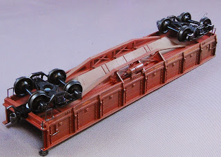
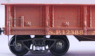
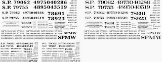
Showing posts with label freight cars. Show all posts

Wednesday, September 23, 2020

More Model Railroad Sudoku: Cow Cars to the Ainsley Cannery

If we want to understand how a railroad and a cannery worked together, we need some data - preferably details about the number and types of freight cars doing to a particular industry. We’d done that in the past with Tom Campbell’s data about the grocery wholesaler’s siding in Sacramento a few years ago, but there’s always more we’d like to learn.


Getting information on the actual freight cars heading off to canneries is always a challenging task. Summary data often survives, either in terms of how many carloads the Santa Clara Valley sent, or canneries bragging about their canning prowess. Lawsuits might suggest the amount of traffic, such as this description of the fruit produced by several canneries. Although I’ve found occasional other facts (such as delivery notifications for freight cars at the Golden Gate cannery), the information’s spotty.

Luckily, occasional gems turn up. The Campbell Museum shared this Ainsley Packing Co. letterhead as part of reminding us of Campbell’s cannery heritage. They were most excited about the letterhead. I was most excited about the contents.

The letter gives the “pear account” of fruit coming to the Ainsley cannery from the Treat Ranch. It’s unclear where this ranch was. One possibility is a 160 acre ranch in Elk Grove run by the Gage family — which would explain why the fruit was arriving by rail on the Southern Pacific. There’s several other Treat Ranches that show up in searches; I’ll let someone else decide on the right one.

We see a carload of pears arriving every couple days from late July through early September. We see multiple carloads on August 3, but otherwise there’s usually a couple days between cars. There’s a larger gap at the end of the season, with 16 days between the arrival on August 24 and September 8.

What do we know about the freight cars? We can use the Official Railway Equipment Register (ORER) to track down what these cars were. The ORER was a frequently-published list describing each railroad's freight cars: reporting marks, size, weight, and special characteristics. Indexes in front can help us identify the owner from reporting marks. It was intended for use by shippers and others to check on the features of the cars they were assigned for loads.

We see 14 cars listed on the Ainsley receipt. (I’ve put them in a Google Docs spreadsheet if you’d like to examine the data in detail.) All are SP or subsidiary cars, suggesting the Treat Ranch was on the SP. Many of the cars come from the Texas subsidiaries, so they may not be familiar to us West Coast SP modelers. The GHSA is Galveston, Harrisburg, and San Antonio Railway, LW is Louisiana and Western, MLT is Morgan’s Louisiana and Texas.

They’re a mix of new and old cars; Most cars at least 15 years old, but two or three are new cars, built in the last few years. The twenty year old CS-2 ventilated fruit boxcars were common, showing up four times. Only one load is carried in a regular boxcar.

Half the freight cars are actually stock cars. I've certainly heard of stock cars being used for carrying fruit in high season. Melons were frequently carried in stock cars as late as the 1950's. However, this is a nice reminder how prevalent use of stock cars was for tree fruit. There’s also several mentions of “boxcar/stockcar” hybrids which I don’t know much about, and couldn’t find pictures.

The use of stockcars as a cheap ventilated boxcar is interesting, and could potentially be fun to model on the Vasona Branch. There's explicit evidence that stock cars carried fruit to canneries in the 1920's. Here's a photo showing workers unloading fruit from stock cars at the Richmond Chase cannery in San Jose. The Feb 1926 reweigh date for the nearest car indicates that apricots were still being carried in stock cars in the late 1920's. Note all the lug boxes are marked with the Richmond-Chase logo. If the cannery supplied the lug boxes, then that probably means the boxes needed to be shipped out to the farm by rail too. Doug Debs also pointed out a 1928 wreck of the Shoreline Limited passenger train at Bayshore involved the train slamming into several stock cars of apricots. The accident overturned the engine and forced some poor soul to go and recover the less-damaged apricots.

So, 14 carloads of pears, and 150 tons of fruit just from Treat. What does that tell us about the total amount of fruit arriving at the loading dock at the Ainsley cannery? How many more cars would have been arriving during the year? We can guess that from some of the news reports about the production at the Ainsley cannery. A 1918 news article, four years after these loads, mentioned that the cannery canned 5.5 million cans of fruit during the season. They spent $300,000 on fruit alone that year. Treat’s $7500 in pears would have been 2 to 2.5% of Ainsley’s total purchase, so if Ainsley bought the same amount of fruit in 1914 (and if all the fruit had the same price), we’d expect the equivalent of 750 cars of fruit coming in during the year, or six cars a day for 120 days. Now, not all of Ainsley’s fruit would have come by train; this is the Santa Clara Valley, after all, so pears, peaches, apricots, and plums would have been arriving by wagon. But I could also imagine that Ainsley would want to lengthen their canning season as long as possible, so bringing in fruit from elsewhere would allow them to can even when the orchards in Campbell weren’t producing. (On the other hand, we’re seeing fruit from Treat Ranch from mid-July to the beginning of September - a pretty wide season already.) It’s easy to assume that we’d have a few cars of fruit a day arriving at the Ainsley cannery throughout the season.

For my model railroad, this information gives me more details about the Ainsley Cannery, and how to make freight operations at the cannery better match what really happened in the 1930’s. First, this data suggests I should have cars coming to the cannery bringing fruit. If Ainsley was receiving fruit from elsewhere in the ‘teens, I can guess they were also receiving fruit from outside the valley in the 1930s. The use of stock cars for fruit is interesting and eye-catching, so I should should build a bunch of SP, EP&SW, and LW stock cars to bring in fruit. Finally, with so many cars coming in from Treat, I should definitely keep the Ainsley cannery busy - pushing many carloads at the industry, and also perhaps considering switching more than once a day to get realistic amounts of fruit into the cannery, and keeping my operators extra busy.

All of the research and guessing I’m doing here can be done for your favorite railroad or industry. Keep an eye out for paper and documentation, or check photos to see if you can spot the cars being loaded or unloaded at your favorite industries. Finding information on specific cars is easier than ever; Google Books has a bunch of ORERs on line. Westerfield also used to sell CDs with scans of particular years. I use Tony Thompson’s Southern Pacific Freight Cars books for more information and photos on the car classes.


Thanks to Ed Gibson for noticing the reweigh date on the stock car in the Richmond Chase photo, confirming that stock cars were used in the 1920's. Thanks to Doug Debs for pointing out the 1928 Bayshore wreck. Most of all, thanks to the Campbell Library for scanning and sharing the letterhead!

Sunday, August 28, 2016

Bureaucratic Railroaders, Paperwork, and Car Locations

Most of us are interested in railroads because of the glamour - gleaming passenger trains running crossing the continent, crews performing dangerous work in good weather and bad, and heroic engineers keeping their train right on the schedule’s times.

Talk to real railroaders, and you’re likely to hear a different message. You’ll hear about all the jobs we don’t model on the railroad. Car clerks typing out waybills. Station agents keeping precise records of the petty cash box. Salesmen taking shippers out for a two martini lunch. Most of all, you'll hear about the bureaucracy needed for a large, distributed company in the days before e-mail. The real railroad was all paperwork, processes to be followed to the letter, and multi-day delays for the simplest of questions.

My glamorous illusions of the railroad got dashed a couple months ago. I’m still looking for information on those Hart gondolas, you see, and a couple Google searches pointed out that the University of Texas, El Paso had a bunch of records from the Southern Pacific’s El Paso shops. Now, I’m unlikely to make it out to El Paso to look at the files in person any time soon, but I’m willing to spend a little bit of cash just in case the records are interesting. I sent the Special Collections librarian a note asking about getting copies of a couple files, and gave them a maximum amount I was willing to spend on photocopies. It took a little while; the SP records don’t appear to be referenced very often, so the library keeps the boxes of material in off-site storage in a warehouse somewhere. But within a month, I got a thick envelope from U.T. El Paso.

That stack of papers in the envelope had a few interesting finds. One file on reinforcing the Hart gondolas in 1927 gave some details about where the Hart gondolas were used on the SP. More amusingly, that particular file told a lot about SP bureaucracy in the 1920’s.

Guess We Better Ask the Big Boss

Excerpt from SP's Campbell, Calif valuation map showing the station and Sunsweet plant

The first bit of bureaucracy involves big expenses. Railroads, like most capital intensive businesses, are very careful about how they spend money. If you’ve ever seen an official Southern Pacific railroad valuation map indicating the location of tracks, signals, and railroad buildings, you’d see that some of the sidings had “G.M.O. 73914” written next to them on the map. These were “General Manager Orders” (probably - I’ve never found an official definition for the acronym). G.M.Os gave official permission to do the big work of laying track, and the original G.M.O. would probably explain exactly why the track must be built. It turns out the G.M.O.s were for more than track; the U.T. El Paso file contained the order allowing the modification of the cars:

Office of General Superintendent, Motive Power, San Francisco, December 26, 1926
Authority for Expenditure of $9,820.00 is requested for the purpose of Improvements to the property as follows:
Reinforce underframe Hart Con-vertible cars, class W-50-3 Series C.P. 10880 to 10959 incl & 12220 to 12239 incl…
These cars were constructed with trussed intermediate sills without proper bracing, thus permitting the bottom of sill to deflect inwards, also drooping of sides.
It is proposed to reinforce cars by applying two additional cross ties, change present location of two cross ties so that intermediate sills will be properly braces laterally at each pair of side stakes between bolsters, also to apply reinforcing plates to intermediate sills.
Authority: General Manager’s letter file 414-0013-2 of August 27, 1924.
… Cost of reinforcing one car:
Material (including percentages): $95.29
Labor (including percentages $80.51
Dr. A&B Acct #55: $173.80
…


Image of G.M.O. order

The records give us an idea of the process of repairing these cars. We now know that these cars were starting to fail in the 1920’s, and we also know how they’re failing - that the sides would droop and sills would deflect. We know the cost - it was worth spending $10,000 to fix a few hundred cars. We know that George McCormick, the superintendent for motive power, was responsible for deciding when to repair freight cars. We know the decision wasn’t a minor one; the railroad's general manager, J. H. Dyer, had to sign off on the purchase because the repairs would cost more than $100 per car. We know the problem had been lingering for a long time - the work had been going on for at least two years, and only only 25 out of 200 cars in this subset had been fixed already. I don’t even want to think of how many meetings McCormick had to sit in arguing whether to do this work or not.

Inter-Office Memo

The second bit of bureaucracy was just the effort of communications, both in the 1920’s and in a physically distributed railroad. In our era of e-mail and iPhones, it’s easy for decisions to be made easily. However the packet of papers had 50 or 60 memos from the El Paso division archives. Some letters asked for updates on progress; the work apparently went slow. On May 4, 1927, the El Paso superintendent sent a response to one of the queries stating that no work had been done on any cars, but they had one car (SP 12281) in the shops for the work. (El Paso was doing better than the Tucson division - A. J. Burke admitted no work had been done on repairing the cars. Like e-mail, memos and letters were often cc'd to relevant people in other divisions, giving the file a view of the Hart repair beyond just El Paso.) Another Hart gondola was loaded with slag and somewhere out on the New Mexico division; Superintendent Irwin ask for the car to be returned ASAP for repair.

By August, budgets must have been getting reworked, for George McCormick in San Francisco asked the divisions to hold off on repairing any more cars on one of the G.M.Os . By September, 46 cars were reported repaired - 16 in Los Angeles, 7 at Bayshore, 14 in Sacramento, 8 at Brooklyn Yard in Portland, 3 in Gerber, and the two in El Paso. I can’t imagine trying to carry on this conversation via a months-long chain of letters, memos, and telegrams. By October 1927, all hundred cars had been repaired, and the GMO was declared complete.

We need to talk about your TPS report covers.

Letter from George McCormick asking about a $15 difference per car in costs billed.

And finally, there was just all the odd little exchanges. A bunch of letters in early 1928 from San Francisco asked R. U. Lipscomb why El Paso spent over expectations on the car repairs.

Auditor of Disbursements advises GMO 71402 now overrun $524 and GMO 71403 overrun $113.00.
The original cost per unit for this work was estimated at $173.80. Los Angeles Shops have verified this figure ample for the 1928 program.
Below is a tabulated list of units in excess of the estimated cost as shown in our records. Please give reason for the increase in cost and state whether this represents cash or second-hand value or if credit adjustment will be arranged. Please give this matter preferred attention.

Ah, nothing more fun than getting e-mails from a manager questioning charges. The El Paso division files includes Lipscomb’s page of math as he figured out the costs to answer his boss, responding ten days later with:

While we have been able to perform work on labor authorized, you will note from the above that the material cost is in excess of amount estimated on Form 30. Set of reinforcements for one car amounted to $100.30. In handling this with the Store Department, they advise this was the cost of one set of reinforcements carried over from 1926 and that the remainder received are invoiced at $85.00”

Even with that bit of information, the questions weren’t ended; two weeks later, McCormick writes back wondering if the Stores cost already includes labor. El Paso responds that the Sacramento Stores apparently double-charged them by including labor costs; L.A. had lower costs because the L.A. accountants were wise to the Sacramento Stores budget tricks. It still took a couple months of mailgrams between A. J. Burke and R. U. Lipscomb in El Paso, Edward Blumenstiel in the El Paso office, and McCormick in the head office before the whole double-charged for $15.00 a car battle ended.

So What Did Those Memos Actually Fix?

Even with all these accounting and responsibility and cover-your-ass memos, there were some nice tidbits for modelers. One of the letters was kind enough to include the L.A. Shops list of parts needed for car repair. (A separate accounting by the El Paso shop superintendent tells us exactly how many bolts and rivets were used on each car. I'm not interested in those because I'm not one of those "rivet counter" model railroaders.)

1.101.33
DescriptionWeightCost
8 Intersill Stiffeners752 lbs @ 2.59 Cwt. $19.48
2 Cross Tie Channels322 lbs. @ 2.60 Cwt. $8.37...
4 Cross Tie Top Plates120 lbs…3.13
8 Intersill Stiffener Fillers42 lbs
4 Stake “U” Bolt Brackets12 lbs0.32
2 Cross Tie Gussets51 lbs
4 Intersill & Cross Tie Connections48 lbs1.25
4 Stake U Bolt Brackets12 lbs0.66
4 Outside Inter Cross Tie Gussets105 lbs0.32
2 Inside Inter-Cross Tie Gussets50 lbs2.74
2 Do 50 lbs1.31
4 Hopper Sill Brackets8 lbs0.21
4 “” “” 5 lbs0.14
4 Hopper Top Plate Supports25 lbs0.65
4 Intersill Reinforcing Places20-130 lbs,3.38
Labor, laying out, shearing, forming and punching…22.65
Labor, apply to car42.16
Shop expense16.10
Use of machinery & tools4.02
Total Labor84.53
Total Cost$141.70

Parts needed for the Hart gondola repairs

And We Also Know Where the Cars Were

So far, all the information I've shared has been pretty dry. The correspondence should be familiar to anyone who's worked at a large company, and it doesn't tell us too much about the models of the W-50-3. The list of parts for strengthening the car might hint at how the W-50-3 class cars changed between construction and later years, although it'll still take a bit of work to understand exactly what changed.

But the file does contain some tidbits that could be very interesting for a model railroader. The letters discussing cars fixed not only documents which shops around the Southern Pacific system performed repairs, but also suggests where the Hart Convertible Gondolas were being used in the 1920's.

41 cars were specifically identified as converted in 1927:

  • 14 at Los Angeles,
  • 6 at Bayshore,
  • 5 in “Southern District” (Los Angeles?)
  • 5 at El Paso,
  • 3 in “Northern District” (Portland? Dunsmuir?)
  • 2 at Tucson,
  • 2 at Sacramento,
  • 2 at Brooklyn (portland),
  • 1 in New Mexico,
  • 1 at Gerber.

These details hint at where those W-50-3s might have been found in the Southern Pacific system. If you model Northern or Southern California, or El Paso, W-50-3 cars should have been visible. If you were in the southwest or Portland, you might see them. If you're in Nevada or Utah, you're out of luck - they're nowhere to be seen. This information doesn't replace photos as evidence for where particular cars or locomotives might have run, but if we're looking for a rough answer about whether the Hart gondolas would have been seen in the Bay Area in the 1920's, this is a good bit of confirmation.

But There's Still More

All this information came only from the first chunk of letters in the files I got from U. T. El Paso. Another 50 pages came from the work to remove home-built snowplows from 7 former El Paso and Southwestern gondolas. The third packet covered GMO 79727, another year's attempt to fix the Hart gondolas.

The last packet had twenty pages documenting the saga of two CS-35A flat cars, SP 79075 and SP 79026. The correspondence was triggered by the cars being used for maintenance-of-way service without officially being charged to the MOW service. By doing so, the SP probably was missing a bit of a tax break by writing off the remaining value of the cars. Every time you letter a car "SPMW", you're actually missing the months of back-and-forth memos needed to throw those cars off the roster of revenue cars.

From George McCormick, back at the head office in San Francisco:

Mr. E. A. Gilbert inspected these cars Jan. 18 at El Paso and found they were assigned to a concrete outfit on the New Mexico Division for sometime past and are permanently fitted suitable for such service, where they should remain. Also it will cost but $5.00 per car to restencil, while cost to return them to revenue service would be approximately $300. each.
Please submit form 30 in the name of Southern Pacific Railroad to convert…”
If you ever dreamed of working on a railroad, I imagine answering telegrams from San Francisco about $10.00 overruns and restenciling cars wasn’t why you wanted to join the railroad. You probably would have had more fun dreaming about being an insurance actuary.

So How Do I Find Records Like These?

Although rare, a few research libraries and archives do have former SP files and drawings in their collections. The files that exist are a tiny fraction of what the railroad kept, but occasionally you can get lucky (like I did here) and find documents relevant for a subject you're either interested in for history research or model building. Generally, find the libraries that might have the correct documents, then look for finding aids which will tell you the actual documents that were saved.

For the SP, common sources are Stanford Library (various records, including freight cars and some land records), California State Railroad Museum, U.C. Berkeley's Bancroft Library, University of Texas El Paso (Rio Grande division), San Francisco Maritime Museum (Southern Pacific ferry records) and California State Railroad Museum. The Online Archive of California website provides a single place to look for relevant collections in many different California libraries.

In each library, you'll be searching for collections - related boxes of records, usually donated together - related to the Southern Pacific. Each collection usually has a "finding aid" - a document that summarizes what records are in a specific collection. In Stanford's finding aid for its Southern Pacific records, you can find exactly which corporate records survived, a list of folders for specific land or track improvement projects, or photos for specific freight cars. With the name of the collection and the identifier for a folder inside that collection, you now can ask the owning library about viewing the material at the library, or, like I did, ask whether they can make a copy of particular materials.


Records from GMO 71402 and GMO 71403 from the Southern Pacific Company (Rio Grande Division) records, MS 077, University of Texas El Paso Special Collections department. Thanks to the librarians who pulled these files out of dusty boxes and photocopied a couple hundred pages of telegrams, mail, and assorted scribblings. Excerpt of Southern Pacific valuation map for Campbell, California excerpted from an original drawing at the California State Railroad Museum Library.

Monday, July 4, 2016

Odd Finds in Dusty Drawers

Part of doing research - historical or otherwise - is the luck of the draw. Who knows what got saved, or what you’ll find if you search in that odd dusty box?

Back in January, I was up at the California State Railroad Museum for another day of research before our annual Bay Area Layout Design and Operations meet. (Thanks to the upcoming Super Bowl booking all the hotels, we got the chance to wander a little farther than usual.) I had a rough idea of documents I wanted to see - some car records for the Hart gondolas, blueprints for the CS-35A flat cars in preparation to refine the design, and drawings for track arrangements at various places in San Jose.

The CSRM is a great research library; the staff are helpful, the rules aren't draconian, and the materials are well-organized and unique. I’ve looked at a lot of freight car plans there over the last year, and I’m still amazed what got saved. There were still holes in the historical record; I might find some blueprints for SP’s Battleship gondolas, but might not find details identifying how the cars were assembled. I might find drawings of New Almaden after they tore down the station in the 1930’s, but little on the arrangement of the tracks in the town’s heyday. It all depended on what SP manager decided to save from the files… or what drawings a railfan pulled out of a dumpster.

I’ve been particularly interested in the arrangement of the brake system for those Hart gondolas I’ve been selling. Personally, the exact arrangement of the brake gear is not the biggest concern for me. For my own models, I’m willing to do something that seems reasonable; as long as the cars look plausible and run well, I’m happy. But when I’m selling the cars, I know that many others do want to get the brake gear precise, and expect that I’ve done the research to make the cars accurate.

The initial kit instructions described a plausible arrangement for the brake gear based on photos and some guesses about arrangements - my best information at the time. However, I’ve always been bugged that I didn’t understand the cars better. Without another source for information, I was stuck.

So take in the scene. I’ve driven two and a half hours up to Sacramento on Friday morning, grabbed a sandwich in Old Sacramento, and I’ve been sitting in the library at the museum since it opened at 1:00. It’s a bit after 4:00 on a Friday afternoon.; the library closes in maybe 45 minutes. I’ve found all the material I’ve wanted, and I’m trying to decide whether to head over early to the Old Spaghetti Factory to socialize with a bunch of other model railroaders, or spend a bit more time looking for anything interesting. I stand up, stretch my legs, and go wandering around the reading room to see what else might be there, and find a three ring binder that’s an index to a bunch of Union Pacific drawings. The index is all handwritten, printed with fat letters done apparently written with a Sharpie and photocopied a couple times; I'm guessing it's a genuine handwritten artifact from the U.P. shop foreman.

I’m ready to discount the contents as modern stuff outside my interests, but I ask Kara, the librarian anyway. “These look interesting; is there any chance I can see these drawings?”

“Oh, we got those years ago. The index never got computerized, and I don’t remember the last time anyone looked at those. The microfilm is over in this cabinet here.” She shows about six file drawers, packed tightly with old-fashioned microfilm rolls. We pick one roll that looks promising, Kara shows how the microfilm loads, and I start looking.

The roll turns out to be a random mix of technical drawings for freight cars, mostly not from my era. I dive in like I’m in Minority Report, quickly checking each image to see if it’s interesting, and learning how much to tap the “forward” button to advance to the next image in a single step. Tap, look, tap, look, tap, look, tap, maybe two or three seconds per image. Part of my speed is just disinterest, but I also realize I’m on a deadline to finish before the library closes.

At 4:50 p.m., I hit pay dirt.

It turns out in 1919, the Union Pacific drew four sheets of drawings for an “Air Brake Folio”, describing the mechanics of the air brake system on a bunch of recent freight cars. For each car, the folio gave some details about braking power and force, formulas for calculating hand brake force, and schematic drawings describing exactly what the brake system looked like. Somehow, those sheets got saved by the UP into the 1970’s when they dumped them but not before microfilming them.

And sheet three includes drawings for the brake systems on Union Pacific’s Hart gondolas.

So I pull out my cell phone and quickly take photos of the interesting bits of the drawing. I also manage to find a couple drawings showing how the Union Pacific lettered their gondolas a few images later. I finished at 5:02. With profuse apologies and thank yous to the staff, I rewind the microfilm and head out the door.

I’ve put details of the brake system up on the Dry Creek Models blog. The drawings give more accurate details for the cars - length of the different rods, and how the brake rodding snakes between the truss supports. One surprising fact is that the Union Pacific cars have an obvious difference from the SP cars. On the SP cars, the brake wheel pulled the piston of the brake cylinder directly - a rod and chain go straight from the piston end over to the brake wheel. On the UP cars, the brake wheel was at the opposite end of the car, and a pulley reversed the direction of the brake chain. According to the Air Brake Folio, UP apparently did this on many of its freight cars (including their version of the H-50-5 hopper and B-50-13 boxcar). If anyone knows why the UP did this, I’d be interested in hearing.

Discovering these drawings is all part of the magic of research - whether for model railroads, or for local history, or for academic, formal history, or even for garage sales. I’m really grateful for all the material that has been indexed or listed in finding aids, for it means I can spot interesting things from my desk at home. However, part of the fun of re-discovering the past is searching in the places that haven’t been curated, indexed, or pored-over by others. I’ve heard that same fun of discovery from a friend searching for depression-era glassware at Goodwill, and from historians like Alex Wellerstein searching the National Archives for the history of nuclear weapons.

And no matter how fun the search might be, we’ll also learn exactly which way the brake cylinder should point on our freight cars.

Oh, if you're curious, here is my original guess about the brake gear layout (as found in the kit instructions), and the brake gear as suggested by the UP engineering drawing:


Air brake drawing from Union Pacific Railroad’s s “Air Brake Folio”, dated March 5, 1919, book 430, drawing 5242-30) , from the California State Railroad Museum.

Wednesday, August 19, 2015

Next 3d Freight Car Model: Southern Pacific's "Battleship" Gondolas

Boy, I've been awfully quiet lately; I'll put at least some of the blame on that 3d printer. Just to show I'm not goofing off, I'll show some of the latest work.

Here's the latest result: Southern Pacific's "Battleship" gondolas. The "battleships" were side-dump ballast cars built around 1902, and they're cool cars from so many different angles.

The Battleships are interesting construction-wise because they're some of the Southern Pacific's early steel freight cars, completely built using steel plate and angles, riveted together. They're sort of like the Eiffel Tower of freight cars in that way - big, metal, and covered in rivets, and they probably impressed the locals at the time for the same reason the Eiffel Tower was impressive. When I saw the plans at the California State Railroad Museum a few weeks back, I found they're just as interesting underneath, with a three foot tall I-beam running down the center of the car, and all sorts of cross-bracing supporting the interior A-frame for the slope sheets.

The cars are also interesting appearance-wise because they look unlike any other freight car. The available photos make the cars look big and boxy, even though they're only 30 feet long - short by modern standards, and even small for my 1930's era. The unusual hinged doors covered each side completely, and the arrangements of hinges catches the eye. Their air-operated mechanism for the side doors are beautifully steampunk with ten foot long operating levers covering the sides.

And finally, the cars were present at the Southern Pacific's greatest battles. The cars were intended to dump fill on each side of a railroad track. Three hundred were bought for the Lucin Cutoff work - Southern Pacific's attempts to tame Utah by running a railroad straight across the Great Salt Lake. They were used in the fill work to block the Colorado River's escaping of its old channel as it tried to fill the Salton Sea. The cars hauled debris away from San Francisco after the Great Earthquake and Fire of 1906. They were used in countless other improvement projects, with some cars lasting into the 1950's in maintenance-of-way service.

These cars were printed on my Form One printer, printed upside down (top to bottom) for easier support during printing. The needed support structure attached along the top rim of the car, and also had individual supports down into the interior. These versions of the model have only been painted with primer and touched up with a bit of putty; I still need to install grab irons, brake gear, and still need to paint and decal the models.

The air-operated mechanism for opening the doors was the touchiest part of the cars to design, and I'm surprised it printed as well as it did. You can see that some of the levers are supported from behind so that the car can be printed in a single piece. I found the lower frame the hardest where shallow angles support the slope sheets that stick out just beyond the edges of the car. The interiors were the fun part because they forced me to fully understand how the car was supported - posts come up from the lower frame to support the top of the car, and a different set of supports braces the door below the hinge point.

Oh, and a pro tip for folks building 3d-printed model railroad models: always take a picture with a coin or X-acto knife. Otherwise, you'll look at your photos and think "wow, that's a lousy model", and then you realize the detail you're complaining about is a literal pinhole.

Sunday, July 12, 2015

3d Printing: New Designs are Hard, Tweaking Designs Is Too Easy

As I’ve been showing off the 3d-printed Hart gondolas, one of the common questions I’ve gotten is “how long does it take to make the design? Could you just scan some commercial model?”

That question goes a lot to the challenge of 3d printing. Although the technology seems magical (“press a button and a freight car comes out”), there’s a huge amount of work to design a model. Having an existing thing - whether a real car or an existing model - doesn’t help. You’d need to get a scan, clean up any imperfections, add detail in the places that didn’t scan well, adjust the design to either exaggerate detail that would get lost when printing at your scale, and hide detail that won't print well.

For example, rivets smaller than about 1.5" diameter don't print well, so I usually do both rivets and bolt heads as 1.5" diameter, 1" tall cylinders. Models with a board floor need gaps drawn in to show off the boards, or require each board to be at a different height to be visible; either choice affects spacing, and how the floor attaches to other parts of the model. Detail that needs to be painted on, such as a metal strap, might need to be raised up so it can be hit with a paint brush. Metal structural parts, such as angle iron, needs to be thickened - 1/4" plate used for stiffening a railroad car would be 3/1000 inch thick - perfectly solid on the prototype, but impossibly flimsy on a model. Changed dimensions might snowball into affecting other parts of the design. Making decisions about how the design should be tweaked requires judgements about what can print reliably, and what detail is essential or unimportant for a model. For lack of a better term, it requires a bit of "art". (Folks making plastic kits have to worry about all these details all the time; check out a plastic boxcar to see the mold maker's choices.)

Fixing an existing scanned design to fix details and make the judgement calls about scale is a ton of work. In many cases, it might be easier to start with a rough idea of what you want to build, and then design from scratch in 3d, just as if you were making technical drawings on paper.

Making a 3d model of a freight car isn’t easy, either. For the three cars I’ve built (the CS-35a flat car, the F-50-4 flat car, and the Hart gondola), I built the models mostly based on photos. I grabbed my copy of Tony Thompson’s “Southern Pacific Freight Cars” book off the shelf, started with any drawings he included, then started guesstimating from the photos. For the CS-35a and F-50-4, Tony included very tiny copies of the original drawings; with these and a good magnifying glass, I could get a decent idea about measurements. With the photos in the book, I could identify some of the details, such as the shape of the stake pockets or guess at dimensions I couldn’t read.

End elevation from Hart gondola plan.

Making the 3d Model from Photos: With the Hart gondola, I had more of a struggle; the Freight Cars book didn’t have any drawings. Tony did include minimal information on car length from an old car description, but other than that, I was on my own. Multiple times, I printed a model, then looked at the photo to compare scale and look for details I missed. The result was pretty good - certainly good enough for my model railroad - but I knew there were mistakes.

So fast forward a couple months, and I’ve decided to try doing another 3d model - this time the Southern Pacific’s “battleship” side dump ballast cars, built in 1902. These cars were critical for the early SP, helping to create the fill across the Great Salt Lake, hauling away the debris from the 1906 San Francisco earthquake and fire, and plugging the Colorado breach to stop the flooding of the Salton Sea. These were huge boxy, coarse steel freight cars that, in every photo, were dumping immeasurable amounts of rock to stop a river or cover a hillside.

For the Battleships, the book only had eight photos, mostly side views. With those, I could get the rough outward appearance. However, the insides weren't visible in any of the photos. I needed to understand how the inside of the hopper was shaped - these had a triangular shapes interior to slide rock to the outside, and those insides would be very visible on the completed model. The photos also hinted that the car was mostly hollow, with support structures underneath holding up that hopper bay. 3d printing promised to get that internal structure just right, so I really wanted to get that non-visible structure correct.

It was time to go to extraordinary lengths.

So last week, I headed up to Sacramento and the California State Railroad Museum to search for more information. The CSRM managed to save many of the plans and blueprints from the Southern Pacific, so for details on obscure, century-old railroad cars, it’s the best hope for information.

Finding the Original Hart Plans: I went up looking for three bits of information. First, when I’d shown off the Hart cars to Tony Thompson last month, he hinted that the cars had been rebuilt in the late ‘teens. “After the rebuild, the cars were two boards higher.” I wanted to find plans for the rebuild so I could make an accurate modern version of the cars. Second, I wanted to find blueprints for the Battleship cars; although I’d been able to print a rough model, I couldn’t see how the frame of the car was built, and wanted to get that right. Finally, I wanted to poke around for more information on San Jose and the canneries.

I wasn’t so lucky with the Battleships and the rebuilt cars; plans for both are stored off-site, and need a week’s notice. (Pro tip: WS and McC call numbers on plans imply they're stored off-site in West Sacramento and McClelland Air Force Base.) However, the staff did find a beautiful set of plans for the original Hart gondolas (last revision, 1918), all on a 30x60 piece of vellum. The drawing is a beauty - some draftsman spent a huge amount of time getting the it perfect, even sketching in the wood grain on some of the posts.

And now I’d put myself in an awkward situation. I already had spent a lot of time on that original model. I’d guess I’ve spent 40-50 hours on it, both in getting the rough design done, and fine-tuning it for printing. And now I had accurate plans, and knew all my mistakes. If I’d scratch built my ten gons, I might have stopped and said “good enough.” If I hadn’t thought that someone else might be interested in the gons, I might have stopped too. But now I knew I had an imprecise model. Worse, I had the ability to change that model.

Detail, Hart gondola door. Note how U bolts and angle iron were used to fabricate the hinges, and note the detail on the door latch that I never could see accurately in the photos.

I sat there for about 20 minutes just looking over the details. Ah, the straps hinging the side doors were actually angle iron, not steel strap. The trusses underneath the car were much deeper (3’) than I thought, and fabricated from larger iron angles. The metal aprons that could be flipped across car gaps only existed on the brake end of the car. I had the length and door spacing slightly wrong. I hadn’t quite understood the mechanism for opening the bottom dump doors.

If you look at the snippet from the drawing, you can see just how much detail is there. There are the revisions about where the handrails go on the car ends. You can see the “v” notch cut into the sides to hold the hinged-up doors. You can identify how metal rods wrapped around each post, then held the posts firm against the frame and truss. You can even see the metal plate joining the side frame and truss, and see the I beam going through the hopper area only joined to the inside of the frames - details I could sort of see in the photo, but now really understand.

Now, it's also worth noting that my original cars weren't that bad. The models I designed were eye-catching and reasonably accurate. The general proportions of the car were good. They're still worlds better than either of the two 1960's plastic or metal kits would have been. Many of the incorrect details I spotted were insanely minor - cases of replacing a metal plate and bolt with a pair of bolts-and-washers, or placing the removable ends just outside of the line of side posts. But I know there are inaccuracies.

So now I’m redoing the Hart gondola - stretching parts correctly, adding details that I hadn’t known about, and hopefully adding some parts of the mechanism. And once that’s done, it’s time to print, paint, and decal some accurate Hart gondolas

I’m still planning on dealing with the “rebuilt” Hart gondolas and the Battleships. I’m going up next week to see those plans. I suspect I’ll be spending a lot of time in front of the computer over the next couple weeks as I pore over some draftsman's really fine work. Stay tuned for more photos of 3d printed freight cars!

Snippets of drawings from Southern Pacific / Union Pacific C-1652 plan, used on SP’s class W-50-3. Last revision April 19, 1918. Original in California State Railroad Museum.

Sunday, February 1, 2015

The Dirty Secret of Printing Freight Cars

BTW, in case you're keeping track, the Hart convertible gondolas were the fourth kind of freight car I printed on the Form One. I've put together a list of all the 3d printed cars I've made, and mention some brief details about each.

With the Hart convertible gondolas, I've finally learned the dirty secret of 3d printing.

Now, if you scratch build a model, it's really easy to make one. You build it slowly; if you get stuck or if something doesn't work, you scrape off the part that isn't working and remake it. Eventually you've got a very nice model. You've also spent a fair amount of time to get to that point. You might be unwilling to make a second, or third, or fourth car because, hey, that would be boring. Making cars only as long as they're fun is fine if you only need one of a particular car, but not so good if you really need a dozen identical cars.

Now, if you were designing an injection-molded freight car, you're definitely aiming at production. You're making either thousands of models for yourself or for others. You'll put a lot of thought into the design because cutting those molds is time-consuming and expensive.

With 3d printing or resin casting, you're in the middle. You're making a small number of items, but you're having to figure out what to make. 3d printing make it easy to sketch up a first model, print it, and iterate. And as a result, you end up with a mighty large scrap box containing all the rejected pieces. Some might be fit only to give you a lesson about things not to do. Other rejected models might be great for a "wreck" at the bottom of a canyon. and some of the rejects aren't so bad...

And now you're in a race. Each time you make a test print, you've made a model that might almost be good enough to use on your layout. You've got some maximum number of models you can probably use on your layout. You've also got ideas on how to tweak each design so that it's closer to perfect and might be useful to other people. So the question is: how fast will you get to "good enough" models and lose interest in printing additional models?

I'm up to twelve or thirteen Hart gondolas at this point, and that's an awful lot for my layout that can't handle more than a hundred freight cars. I've got four cars modeling the gondolas with the bottom doors shut; they look pretty good, but the side sills are too short and won't fit the 7" lettering for reporting marks. So I'm caught - do I use these cars even though they're not quite right, or do I print another four or five cars to get perfection?

Printing a Freight Car: Hart Convertible Gondola (SP W-50-3)

In Silicon Valley, there's two kinds of semiconductor chip companies. Some companies that design their own chips, then make those chips in their "fab" -- their billion-dollar factory. Then there are companies that just make a design, and sell you the design so you can make the chips yourself. Intel is a good example of the first; ARM (the folks who make the core of iPhones) are examples of the second.

The same was true in the railroad industry. If you wanted a freight car, you could go to American Car and Foundry, and say "give me a hundred boxcars". They'd make you a hundred boxcars. Then there were other companies like Rodger Ballast Car Company. You'd call up Rodger and say "I want a hundred gondolas"; they'd hand you a set of plans and say "here's the design, go get someone else to make the cars, because we're too busy playing pinochle."

The Rodgers Ballast Car Company, as their name says, specialized in the design of freight cars for maintaining railroads - open top gondola cars for carrying the ballast rock that holds railroad track in place, or carries the rail, or carries whatever else was needed for laying down new track or repairing old track. They were particularly well known for the "Hart Convertible Gondola", the Transformer of their era. On the outside, the Hart gondola looked like a slightly odd freight car, with a strange truss frame underneath. If you wanted to carry rail or ties, you'd use it as-is. Now, imagine you've laid some railroad track, and you need to put crushed rock between the ties. You'd then open some secret hidden doors in the bed of the gondola, and it would expose a hopper that could spill rock out between the rails. You'd fill the Hart gondola with rock, send it down the track with the hopper partially open, and distribute the rock neatly. But what if you were trying to add dirt to a filled-in area along the tracks? Well, close those center doors, and instead release some side doors, and you can now spill dirt on either side of the car.

If you're feeling particularly energetic, you can set up a line of cars with a continuous line of dirt. (The cars had hinged aprons that could bridge the space between cars, and had end sections that could be removed altogether.) Now, you can put a plow that's just as wide as the inside of the car at one end of a string of cars, and stretch a cable across all the cars to a winch at the far end. Now, power up that winch and pull the plow through all that dirt, and it'll all dump out on the sides of the car as neat as can be! If you ever wanted a freight car with tons of play value, the Hart Convertible gondola is just what you need.

And if you're thinking that the Hart gondola is starting to sound like a prank, go check out the patent to see how Mr. Hart himself described it.

The Model:

Detail of 3d printed Hart gon.

Now, the Hart convertible gondola was a popular design, with railroads across the U.S. using Rodgers' design. Unfortunately, because each railroad could tweak the plans, the designs all tend to have slight differences. They're also surprisingly rare in the model world; there were some plastic models of the Hart gondola created back in the 1960's, but few other attempts to recreate the cars.

The Southern Pacific did have around five hundred of these cars which they used for construction all across the system. These cars (with the catchy names of "W-50-1" and "W-50-3") would have been common in my 1930's era. Their pronounced underframes also mean they're eye-catching models. All the complications that make them inappropriate models for mass production. The truss, the hinged doors, and hoppers underneath would make them hard to do as injection-molded parts. However, all those complications aren't a problem for 3d printing. I also wasn't interested in scratch building one or two cars. A good work train would require several of these cars. All these requirements make 3d printing these cars the right solution.

Underframe with trusses and hopper printed in one piece.

Interior with hopper, doors, hinged aprons, and support beams in hopper bottom visible.

Like the CS-35A flat car models, I designed my Hart gondolas in SketchUp, the architectural drawing program. I started off with a simple model with only the rough underframe and shape, but left off much of the detail: grooves between board, minor fittings, and pilot holes for placing grab irons. I also left off the doors in the floor and the ends because I assumed I wanted to print these separately to make different configurations of the car. That didn't work so well; although I could print the hopper doors separately, gluing them in was messy and didn't look good. Later versions had one model with the doors up and another with the doors down - both were easy to print. I also wanted to leave off the ends so I could have models with the end walls at the end of the car, next to the hopper, or removed completely. I'd started by printing the ends separately. However, my printed versions warped, so I made new doors out of plastic sheet. The brake cylinder is unusually visible - it's attached to the outside edge of the car. Because printing the brake cylinder as part of the body would have been hard to support, I ended up gluing one on later. I'd already done a brake cylinder part for my flatcar models, so I had an unending supply of castings!

There's a bunch of tiny detail on these cars. Each each time I look at a photo of the real thing, I see more details I missed. In some cases, I added the new detail; in other cases, I've decided the model is good enough as it is. For example, I noticed early on I missed the mechanism for latching the side doors shut. In the large side photo, you'll see some sort of bracket on each post, and a square detail on each side door. This supported a bail mechanism. A piece of pipe was bent so that it went around each post and against each door. When the pipe was rotated one way, it would touch the door and the latch; rotated the other way, the bail would move away from the latch and let the door swing open. Many of the 1930's photos seem to show the mechanism gone; I left it off of my models for now. I've also noticed that the brake wheel (mounted on the end of one of the sides) had a rachet mechanism on top of the car; that deserves to be added.

The next step was to figure out how to print these cars. With the flat cars, I figured out that 36 foot cars could be printed flat on the printer's build platform. When I started printing 40 foot flat cars, I had to tip the cars at an angle to fit. With the gondola's raised sides, even tipping the car wouldn't let them fit in the build area. I tried printing some at 45 degree angle without much luck and with a lot of wasted resin for the support structure.

Five gondolas as they're removed from the 3d printer.

I finally realized that while I didn't have side-to-side space for the car, I did have vertical space - my Form One printer could print up to around a 45 foot car. So I removed some of the fine detail from one end of the car, and printed it vertically, pulling the car out of the resin tank layer by layer. Once I figured out I could do that, I also proved I could print four or five at once at a fraction of the time - printing one requires about 12 hours and $3.00 of resin, but printing five took 20 hours (4 hours a car). Woohoo!

Note flaws along posts in this model. Because the posts suddenly jut out, their initial layers are unsupported and may not adhere to later layers.

Printing the cars vertically required leaving the ends off the car. When printing vertically, anything going up and down (parallel to the sides) prints fine, but new pieces cutting across the middle either bridging the sides or sticking out from the sides work less well. (They'll work with gentle angles, but not with 90 degree projections, though there are ways to get support structures to help support the bridges.) The problems with crosswise pieces ensured I made the ends as separate pieces.

The Form One still can do some pretty amazing things - look both at the truss under frame, at the cross bracing in the truss, and at the support beam in the interior of the hopper. That's some very tiny work, and somehow the printer is able to make it cleanly!

Version with doors down

So what's been good with these cars?

  • The W-50-3 prints as a single body. Once it's printed, I just need to clean up the casting, drill and tap holes, add grab irons, and paint the finished car.
  • They're not insanely expensive. Printing these at Shapeways would have cost around $50 because of their better machines, but I could do these cars inexpensively at home - $3.00 in material, with machine time and cleanup time as biggest additional costs.
  • The 3d process makes it easy to do the variants. I could have just as easily made some with side doors swung out, or with dump doors open, or imitate the W-50-1 class's steel fishbelly sides. I've even printed an N scale car body from the design.
  • I reused the brake cylinder piece I'd already modeled and printed with the 3d printer.
  • My car's quality is close to injection molding, and certainly good enough for my purposes. There's enough detail to make me think the cars are detailed, and they stand up well against the other freight cars in my fleet. I can also print enough cars to support work train operations on my layout.

What wasn't so good?

  • I omitted some of the detail from my model - the chains that open the doors below, bars that latch the sides shut. Some of this wouldn't be a significant problem to add; in other cases (such as the chains), 3d printing might not help.
  • Because I'm printing from one end, the starting end's lacks some detail. So far it hasn't been a concern for me.
  • The clear resin I used for these models is a bit more fragile than a resin kit, and may break if dropped. The gray resin appears more flexible; I need to print a couple cars in gray.
Looks like a success. I've got five cars near ready to go, with another seven needing decals. I'm also looking forward to adding loads for some of the cars; as nice as the open hoppers look, I'd really like to fill some partially with gravel, and put rail and ties in some of the models with closed doors. More pictures as I finish the rest of the cars!

Patent image from U.S. Patent 941249. Prototype photo from Mid-Continent Railway Museum's article on a Hart gondola in their collection.

Thursday, January 8, 2015

Hart Convertible Gondola (SP W-50-3): Another Sneak Preview

Yep, it's time for another sneak preview of my Hart convertible gondolas, printed on the Form One 3d printer.

Did I mention that I'd figured out how to print five gondolas at once?

The painted cars here are the first version of the design; the cars in back have the hopper doors closed. I've printed got a second version of this model with even more detail. It's now a race - will I have enough "good enough" cars that I won't bother to get the design perfect?

I've got an article on these models ready to go, but I'd like to do a couple good paint jobs and decal one of these models before sharing more.

Sunday, September 21, 2014

Printing a Freight Car: Southern Pacific CS-35A Flat Car

I’ll admit it. I’m not a freight car modeler. Sure, I’ve had an appreciation for appropriate freight cars from my era, and I’ve built a lot of resin kits for the Vasona Branch. But I’m not one of those folks who could argue the difference between the different patent pressed-car ends, or could tell you what percentage of B-50-14 boxcars had Bosendorfer side doors, or would argue about the appropriate underframe for a stock car. But, hey, all that goes out the door when I decide to print freight cars on the 3d printer.

My list of potential 3d-printer projects has always included a few freight cars. As popular as the Southern Pacific may be, modeling the 1930’s means building a lot of resin kits, searching eBay for old kits, or finding a lot of stand-ins. One example would be the Hart convertible gondolas, frequently used for dumping ballast on railroad tracks. Another would be flat cars - Southern Pacific’s 1930-era flat cars look much more fragile than the typical 1950’s plastic flat car kit that’s available, and tended to have a very specific look. More importantly, I needed flat cars for the Vasona Branch - lumber coming from the sawmill at Laurel needed to come down the hill to the lumberyard at Auzerais St.

I’d hoped my first-generation Makerbot was going to help me with freight cars, but it couldn’t print something that looked good at HO scale - the layers in the plastic were too obvious. The Makerbot could only print within a 4 inch cube - not big enough for even a smaller flatcar. The Form One, though, was getting big enough. At 125 mm x 125 mm x 165 mm, the printer could print a 36 foot freight car diagonally, or a longer car if I tilted it up on end. So, soon after I’d gotten the Form One up and printing, I tried a couple flat cars. Here’s the details on that first flat car.

The Prototype: Southern Pacific CS-35A Flat Car

In 1903, the Southern Pacific decided to experiment with freight cars built completely of steel. Two plans appeared that year: the CS-35 car (36 feet long with 40 ton capacity) and the CS-35A car (40 feet long, 40 tons). Both these CS (Common Standard) cars represented first attempts at a flat car with a steel under frame: a pair of 15 inch I-beams along the center, and pressed steel sides tied together by a 19 inch deep C-channel. The two designs were apparently in a bake-off; both designs date from October 1903, but only the CS-35A got the green light. SP had 1,000 of the 40 foot cars built by the Pressed Steel Car Co. in Chicago.

The CS-35A, designed during the Harriman era, differed from later flatcars such as the F-50-2 by having only nine stake pockets on each side compared to eleven or twelve on later cars. Other spotting features was the lack of rivets on the bottom edge (unnecessary in the stamped forms of the early cars, but needed in the fabricated side frames of later cars) and twelve rivets on the side at each truck bolster.

These flat cars definitely looked different from the other standard SP freight cars - relatively shallow sides, no truss rods, and longer than most of SP’s flat cars. Compared with modern freight cars, they look positively wispy and fragile. They also lasted a long time, with Tony Thompson’s SP Freight Cars book showing the cars still in common use in the 1920’s, both for revenue service and for maintenance.

Of course, there’s no models of the CS-35A available, whether as a resin kit or plastic model, so it was a great first try for 3d printing.

The Model

The first question was how to build the model - do I try to print the whole freight car in a single piece? I’d seen models on Shapeways where only the metal parts were 3d printed; the wooden deck for the flat car was done with laser cut wood. That seemed great; the wood deck would be more realistic, and I could print the model upside down on the build platform. (That didn’t work; more later.) I tried doing a couple models where only the frame of the flat car was printed, with big openings below. That didn’t work - the printed piece ended up being too thin to print, and wasn’t strong enough to survive removal. I ended up building the model so the top was solid and 6mm thick; the wood deck would be glued onto that surface.

I did the initial drawing for the CS-35 in SketchUp. I started out sketching the rough shape, extruded it as a 6 scale inch thick slab, then started adding details - first the frame and ends, then more and more detail. I scaled the sides so they were 6 inches thick and printed more reliably. For details - stake pockets and patterns of rivets - I often drew the objects in a separate SketchUp model, then made the object into a group and pasted copies into the final model. I learned that 1” diameter cylinders, 1 inch high, made great rivets. I also marked the holes for grab irons by drawing a 1.5 inch diameter hole.

There were also details I didn’t model. I didn’t add brake gear to my initial model. I planned on using wire grab irons, and grabbed brake wheels from my scrap box. I did need to model the brake cylinder for the car; it’s obvious on all the real photos I’ve seen. I started using the Tichy Train Group’s K Brake kit, and bought a half dozen at my local model railroad shop, but found I was only using the brake cylinder. I ended up building a 3d model for the brake cylinder, and printing the brake cylinder myself.

One of my other surprises when building this was the question of what exactly to build. Any model has compromises - I might not want to add all details, or I might need to change a dimension, or I might tweak the model to fit a model railroad coupler. Figuring out these differences between the model and the real thing is the hard part of making a model, whether by hand, with a 3d printer, or when designing an injection-molded kit. For the CS-35A, I had to decide whether to add some of the underbody beams and braces (no), or what detail to add to the ends (minimal.) I also had to choose between scale dimensions and a reliably-printing model. I ended up making the center I-beam much thicker than in real life so it would print more reliably. Instead of 1 inch, I made all the walls 2 inches thick. I also drew it with slopes inside the I so there wasn’t a difficult transition from thin to full-width.

Flat car and support structure. Support structure holds car at 30 degree angle to avoid any horizontal slice through the middle being too large.

I also had hiccups. I had problems printing the final model because of extra hidden faces; I used Netfabb Basic to clean up the models and prepare them for printing. Even that didn’t work reliably. Because of the Form One’s resolution, making a “watertight” model (no holes or gaps between faces) was critical. On the Makerbot, the low resolution meant holes would usually be ignored when breaking the model into layers. With the tinier resolution, even a small hole could convince the Form One software that you intended the model to actually be hollow. I also found that pieces thinner than 2 scale inches (0.020 inches, or 0.5mm) didn’t print reliably. (The design rules from Shapeways for their frosted ultra detail material have similar limitations.) I found I couldn’t print the freight cars flat on the build surface either without layers failing to bond. Formlabs, the maker of the printer, suggests that large flat prints be done at an angle so that any individual printing layer doesn’t cover a large area. Doing so gave me more reliable printing, but doubled print time. I also found I needed to be careful about cleaning the model - I’d been leaving the finished prints in direct sun to cure, but had problems with warping. Keeping time in the sun short, and making sure both sides were exposed to the sun helped limit warping.

Initial model. Note messed up corner caused by deformation when printing near edge. The other cars weren't this bad, but all cars printed with the long edge tipped had a bit of deformation.

The overall process for printing the flat cars was something like this. First, I’d print a couple models over a day or two. Like all the 3d models, I’d pull them out of the printers, remove them from the build platform, and soak them in isopropyl alcohol to wash away the extra resin. I’d remove the support structure added to print the model, then leave the models in the sun for 10-20 minutes on a side. Another day, I’d spray paint the models (Scalecoat boxcar red in a spray can). I’d drill out holes for the screws holding on the trucks and couplers, then attach both with plastic screws, and cut the screws off flush with the top surface. I’d then add a wood deck using individual 2x8 wood boards stained with india ink and alcohol, gluing them on with contact cement. I decaled the cars, then then drilled holes for wires representing grab irons and superglue them in place and touched up the paint on the grab irons. A final spray of Dullcote sealed the decals onto the model.

I made a couple embarrassing mistakes with the model. On my first try, I used the plans in Tony Thompson’s “Southern Pacific Freight Cars” book to build the CS-35 36 foot car. That model turned out well (and the 3d model is available on Thingiverse). When I went to decal the model, I looked for the car numbers for the 36 foot cars… and realized there were none listed - SP never built any. I'd been printing the Loch Ness Monster of SP flatcars.

To correct my mistake, I stretched the design out to make a 40 foot car. In SketchUp, this wasn't too challenging; I'd select the portions of the flat car from the bolster out, then use the move tool to drag these out the appropriate distance. After I printed a few of the longer cars, I compared them against photos, and realized the model didn’t look right - the wheels were set closer to the center of the cars. The CS-35A looked a bit like the ends of the cars were unsupported. I went back to SketchUp, and moved the truck bolsters in.

The final model requires about 15 cubic centimeters of resin and prints in three and a half hours. The resin cost about 15 cents a cubic centimeter, and about half gets lost during printing and cleaning, so we’re talking about $3 in resin per freight car. Compared to Shapeways, which would charge around $30 for a similar part, it’s not a bad deal. On the other hand, I went through a lot of prints for testing - probably 10 to 12 pieces. Once I got the design and printing settings done, it was easy to print more flat car castings on demand.

I still have some minor problems with warping, and the arrangement of the model usually causes one corner to be bent in a bit. Both they’re still fine models,and I’ll be able to make some reasonable 1930’s flat cars for my layout quickly. One potentially big problem is that the models are very light - only about 1.5 ounces with trucks and couplers, much lighter than the recommended 3.5 ounces. I’m planning to either add weight to the loads on the flatcars, or add some lead sheeting in parts of the model.

The Decals I printed and decaled one of the “wrong truck spacing” cars using a mix of leftover details; that process was amazingly painful. I tried finding some commercial decals that had the needed freight car numbers and tiny lettering, but didn’t find any good sheets at my hobby shop. I ended up deciding that custom decals might be reasonable, especially if I was going to build ten cars.

I drew up the artwork in Intaglio (a vector drawing program like Adobe Illustrator). I tried using Ben Coifman’s Railroad Roman font which I’d bought years ago, but its lettering looked a bit thinner than the stock SP lettering style. I ended up doing half the sheet using the Baskerville font available on the Mac which resembled the SP lettering, but had thicker letters. The bolder glyphs should make it easier to read the cars in my dark garage.

I sent the decals off to Rail Graphics; my 1 inch by 4 inch decal sheet cost $50 for a run of 50 decals, each with enough lettering to cover a few cars. The finest 2 inch tall lettering isn’t legible, but all the other lettering was readable and fine for my cars.

I’d never seen any hints on making custom decals, but designing my first sheet gave me a few lessons. First and most important, I made sure that the car numbers included a bunch of optional numbers that matched the real cars. For my CS-35A cars, car numbers would have been between 78500 and 79499. I added several numbers starting with 78/79, and also made sure that numbers starting with 48, 49, and 40 existed in case I wanted to do some of the other SP flat cars. I added several different car lengths and weight capacities so I could do some of the alternates. I also added the SPMW lettering in case I wanted to model any of the maintenance of way cars seen in photos.

I didn’t think about the difficulty of cutting the decal apart. The lettering on these decals was remarkably tiny; I had to borrow my wife’s Optivisor to be able to cut them apart. I put the “feature” lettering - “dirt collector”, “metal brake beam”, etc. on a single line, so it was easy to cut a strip out, then break out the individual words. For the other lettering such as the reweigh information, I did a lot of cutting out individual words. I wish I’d put most of the data for a single kind of car on a single line so I could cut that line off the decal sheet, then cut the individual pieces off separately.

Oh, and if you decal one car by hand before doing the custom decals, don’t use that number on the decal sheet.

The Final Models

So far, I’ve built six of these cars - two of the non-existent 36’ CS-35 cars, one of the CS-35A cars with the wrong truck spacing, and three of the 40’ CS-35A cars with the correct truck spacing. I also have one model that I had printed by Shapeways in Frosted Detail (the lower-quality.) They’re fine cars for my layout. They look positively fragile next to the chunkier Athearn 40 foot flat cars, and I also know that they’re historically accurate.

What’s next? I also like the look of the SP F-50-4 cars, with their narrow sides but prominent center beam. I’ll show more of my progress on those later. I’m also seeing about building models of the W-50-3 Hart convertible gondolas used in ballast service. Keep your fingers crossed that I can print those reliably.

And finally, let's check out the cars in action:

Monday, July 14, 2014

Sneak Preview: 3d Printed Flat Car

Here's a preview for a future article: a 3d-printed Southern Pacific CS-35 flat car, circa 1903. I printed this on the Form One resin printer. The deck of flat car is individual pieces of stripwood, stained with india ink.

My obvious mistakes:
  • wrong number of stake pockets (should be 8 per side, not 9).
  • set of 12 rivets over trucks should be 6.
  • Deck is too narrow - the wood should stick out a few inches beyond the frame.
  • The CS-35 was made of fabricated steel components, and should have a hard edge on the bottom edges of the side. The curves are appropriate for the CS-35A, which used pressed steel components.
  • The car never really existed, it seems.

That last point was the killer. Tony Thompson's Freight Cars book shows two sets of plans for the CS-35 and CS-35A; only after I built it did I notice that niggling detail that there was no other mention of the CS-35 in the book. The 36' CS-35 was never built; instead, the SP went with the similar 40' CS-35A. Making a design for the CS-35A involved selecting each end of the car in SketchUp, and dragging it out to the proper length.

It's also been a pain to figure out how to print these reliably - to fit on the build platform, each is printed while leaning 20 degrees to the side. But I've now got castings for both the 36 and 40 foot cars. Once I've added a bit more detail on the underside, I can print enough freight cars to keep the Santa Clara Valley Mill and Lumber mill on San Carlos Street busy.

Monday, May 7, 2012

Why I Model the 1920's

As much as I'd like it to be true, "why do you model the 1920's" isn't the most common question I hear about the Vasona Branch layout. "How long have you been building it?" or "You've got trains in your garage?!" probably are the most common questions. But I wish it were.

And here's one reason why. Here's the photo of Del Monte's dried fruit packing plant, Plant 51, after a recent operating session. That's 9 cars on the siding. There's room for another six (and it appears busy, not crowded.) Some crew is going to get lost navigating between those cars trying to figure out what they're pulling out today.

Here's the photo with modern cars. Eight cars, room for another three, and the scene's looking a little bit overstuffed.

That's called more fun per unit area.

[Modern boxcars and covered hoppers courtesy of teenage me. The silver Swift reefer was on my original HO Bachman loop of track.]

Thursday, July 14, 2011

Freight Car Research: 1935 Lawsuit Hints at San Jose Freight Cars

Man, those modern railroaders have it good. If they're curious what kinds of freight cars are in trains, they go to the tracks and take photos. If they're curious about how locomotives travel around, they visit one of the tracking sites to see where UP 5623 is. They've got Street View, aerial photos, etc.

That doesn't work as well for those of us modeling the past. If we want to set a scene, we have to search dusty archives, examine the background of old photos, and dig a lot deeper for not very much information.

For example, what did the freight cars look like along the tracks in San Jose in the 1930's? Should I have a lot of Southern Pacific boxcars on my layout, or a few? Were the boxcars old, or were the new steel boxcars appearing?

Some photos (such as this photo of Del Monte's Plant 51 can hint at the question. We see lots of single sheathed boxcars, and the front two boxcars are both Texas and New Orleans (a SP subsidiary), but there's so many questions left unanswered - how fast did the cars turn over? What are those cars in the back? Where are the cars going?

Luckily, there are some other sources. Tom Campbell, who models R Street in Sacramento, was doing research on what his area looked like in the 1950's, and along the way found out about a fight whether the SP had to switch cars from the Western Pacific going to a local grocery distributor.

The California Railroad Commission case over this issue included, as evidence, a list of all the freight cars that arrived at Valley Wholesale Grocery's spur from January 1935 to June 1936. Tom and I made a spreadsheet of the cars so we could sort them by railroad, origin, delivery date, or even what kind of car it was. Check out the spreadsheet and background document.

Here's some of the surprising facts I learned from the data. What do you see? Post here, or on Tom's blog entry about Valley Wholesale Grocery.

* There were 170 cars delivered to Valley Wholesale Grocery over about a year and a half. That's a new car arriving every three days for a short spur sandwiched between two other industries. That's a reasonable rate, even for a model railroad. The majority of the cars (140/170) were SP, T&NO, and PFE, with many of the cars coming from elsewhere in Northern and Central California.

* 57 of the 170 cars are, I suspect, evaporated milk and other milk products from milk plants in Ripon, Modesto, Gustine, and Galt. I didn't know that evaporated milk was so popular in the 1930's, or that it was often used as a base for infant formula.

*31 of the 170 cars are from South Vallejo, and arrive weekly. My first guess is this is flour and other products; there had been a General Mills mill there; it burned in August 1934. Time to check out some period Sanborn maps for ideas.

* Twelve cars came from Battle Creek, Michigan, and at least one was from General Foods (aka Postum), bringing probably Post cereal, Jell-O, Maxwell House coffee, and Postum. Some of these were 50' auto boxcars with larger doors intended for carrying partially disassembled wagons and automobiles. The long cars were probably good for the light and bulky packaged foods. I've got a few 50 foot boxcars on my layout, but I only use them on team tracks. I suspect they'd also be useful at some of the dried fruit packing plants, carrying Sunsweet prunes off to an eager public!

* Two of the cars came from Palacios, Texas, on the Texas coast. Palacios was a big shrimp port, so it seems like Sacramento must have liked their canned shrimp!

* All the cars from Gustine, the location of the large Carnation Milk Products cannery, were refrigerator cars. Most of the other delivered cars were boxcars. What did Valley Wholesale get in refrigerator cars? It doesn't look like they had any kind of refrigeration in the warehouse, though there was an ice cream maker in the next building in the 1950's.

* What's that Norfolk and Western coal hopper doing in Sacramento, just arrived from Peoria? Was it a typo by the railroads or California Railroad Commission, or did they heat the building with coal at the time?

So what does all this tell me about freight cars for the Vasona Branch?
* More Southern Pacific freight cars. Valley Wholesale Grocery may not be representative of my canneries, but it suggests a lot of SP cars stayed on the SP.
* More T&NO cars. There was one T&NO car arriving for every Southern Pacific car.
* More single-sheathed, outside-braced boxcars. They're about half of the boxcar fleet seen.
* Use the 50 foot auto boxcars for the packing houses sparingly.

Time to build more cars!