


In Silicon Valley, there's two kinds of semiconductor chip companies. Some companies that design their own chips, then make those chips in their "fab" -- their billion-dollar factory. Then there are companies that just make a design, and sell you the design so you can make the chips yourself. Intel is a good example of the first; ARM (the folks who make the core of iPhones) are examples of the second.

The same was true in the railroad industry. If you wanted a freight car, you could go to American Car and Foundry, and say "give me a hundred boxcars". They'd make you a hundred boxcars. Then there were other companies like Rodger Ballast Car Company. You'd call up Rodger and say "I want a hundred gondolas"; they'd hand you a set of plans and say "here's the design, go get someone else to make the cars, because we're too busy playing pinochle."

The Rodgers Ballast Car Company, as their name says, specialized in the design of freight cars for maintaining railroads - open top gondola cars for carrying the ballast rock that holds railroad track in place, or carries the rail, or carries whatever else was needed for laying down new track or repairing old track. They were particularly well known for the "Hart Convertible Gondola", the Transformer of their era. On the outside, the Hart gondola looked like a slightly odd freight car, with a strange truss frame underneath. If you wanted to carry rail or ties, you'd use it as-is. Now, imagine you've laid some railroad track, and you need to put crushed rock between the ties. You'd then open some secret hidden doors in the bed of the gondola, and it would expose a hopper that could spill rock out between the rails. You'd fill the Hart gondola with rock, send it down the track with the hopper partially open, and distribute the rock neatly. But what if you were trying to add dirt to a filled-in area along the tracks? Well, close those center doors, and instead release some side doors, and you can now spill dirt on either side of the car.
If you're feeling particularly energetic, you can set up a line of cars with a continuous line of dirt. (The cars had hinged aprons that could bridge the space between cars, and had end sections that could be removed altogether.) Now, you can put a plow that's just as wide as the inside of the car at one end of a string of cars, and stretch a cable across all the cars to a winch at the far end. Now, power up that winch and pull the plow through all that dirt, and it'll all dump out on the sides of the car as neat as can be! If you ever wanted a freight car with tons of play value, the Hart Convertible gondola is just what you need.
And if you're thinking that the Hart gondola is starting to sound like a prank, go check out the patent to see how Mr. Hart himself described it.
The Model:

Detail of 3d printed Hart gon.
Now, the Hart convertible gondola was a popular design, with railroads across the U.S. using Rodgers' design. Unfortunately, because each railroad could tweak the plans, the designs all tend to have slight differences. They're also surprisingly rare in the model world; there were some plastic models of the Hart gondola created back in the 1960's, but few other attempts to recreate the cars.
The Southern Pacific did have around five hundred of these cars which they used for construction all across the system. These cars (with the catchy names of "W-50-1" and "W-50-3") would have been common in my 1930's era. Their pronounced underframes also mean they're eye-catching models. All the complications that make them inappropriate models for mass production. The truss, the hinged doors, and hoppers underneath would make them hard to do as injection-molded parts. However, all those complications aren't a problem for 3d printing. I also wasn't interested in scratch building one or two cars. A good work train would require several of these cars. All these requirements make 3d printing these cars the right solution.

Underframe with trusses and hopper printed in one piece.

Interior with hopper, doors, hinged aprons, and support beams in hopper bottom visible.
Like the CS-35A flat car models, I designed my Hart gondolas in SketchUp, the architectural drawing program. I started off with a simple model with only the rough underframe and shape, but left off much of the detail: grooves between board, minor fittings, and pilot holes for placing grab irons. I also left off the doors in the floor and the ends because I assumed I wanted to print these separately to make different configurations of the car. That didn't work so well; although I could print the hopper doors separately, gluing them in was messy and didn't look good. Later versions had one model with the doors up and another with the doors down - both were easy to print. I also wanted to leave off the ends so I could have models with the end walls at the end of the car, next to the hopper, or removed completely. I'd started by printing the ends separately. However, my printed versions warped, so I made new doors out of plastic sheet. The brake cylinder is unusually visible - it's attached to the outside edge of the car. Because printing the brake cylinder as part of the body would have been hard to support, I ended up gluing one on later. I'd already done a brake cylinder part for my flatcar models, so I had an unending supply of castings!
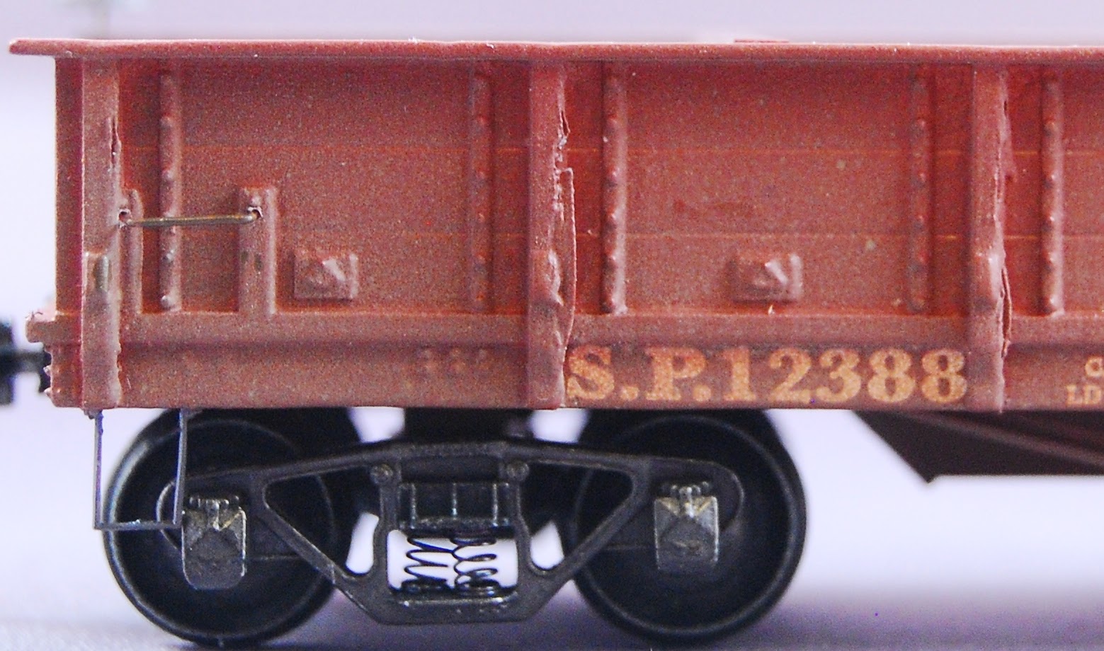
There's a bunch of tiny detail on these cars. Each each time I look at a photo of the real thing, I see more details I missed. In some cases, I added the new detail; in other cases, I've decided the model is good enough as it is. For example, I noticed early on I missed the mechanism for latching the side doors shut. In the large side photo, you'll see some sort of bracket on each post, and a square detail on each side door. This supported a bail mechanism. A piece of pipe was bent so that it went around each post and against each door. When the pipe was rotated one way, it would touch the door and the latch; rotated the other way, the bail would move away from the latch and let the door swing open. Many of the 1930's photos seem to show the mechanism gone; I left it off of my models for now. I've also noticed that the brake wheel (mounted on the end of one of the sides) had a rachet mechanism on top of the car; that deserves to be added.
The next step was to figure out how to print these cars. With the flat cars, I figured out that 36 foot cars could be printed flat on the printer's build platform. When I started printing 40 foot flat cars, I had to tip the cars at an angle to fit. With the gondola's raised sides, even tipping the car wouldn't let them fit in the build area. I tried printing some at 45 degree angle without much luck and with a lot of wasted resin for the support structure.

Five gondolas as they're removed from the 3d printer.
I finally realized that while I didn't have side-to-side space for the car, I did have vertical space - my Form One printer could print up to around a 45 foot car. So I removed some of the fine detail from one end of the car, and printed it vertically, pulling the car out of the resin tank layer by layer. Once I figured out I could do that, I also proved I could print four or five at once at a fraction of the time - printing one requires about 12 hours and $3.00 of resin, but printing five took 20 hours (4 hours a car). Woohoo!
Note flaws along posts in this model. Because the posts suddenly jut out, their initial layers are unsupported and may not adhere to later layers.
The Form One still can do some pretty amazing things - look both at the truss under frame, at the cross bracing in the truss, and at the support beam in the interior of the hopper. That's some very tiny work, and somehow the printer is able to make it cleanly!

Version with doors down
So what's been good with these cars?
- The W-50-3 prints as a single body. Once it's printed, I just need to clean up the casting, drill and tap holes, add grab irons, and paint the finished car.
- They're not insanely expensive. Printing these at Shapeways would have cost around $50 because of their better machines, but I could do these cars inexpensively at home - $3.00 in material, with machine time and cleanup time as biggest additional costs.
- The 3d process makes it easy to do the variants. I could have just as easily made some with side doors swung out, or with dump doors open, or imitate the W-50-1 class's steel fishbelly sides. I've even printed an N scale car body from the design.
- I reused the brake cylinder piece I'd already modeled and printed with the 3d printer.
- My car's quality is close to injection molding, and certainly good enough for my purposes. There's enough detail to make me think the cars are detailed, and they stand up well against the other freight cars in my fleet. I can also print enough cars to support work train operations on my layout.
What wasn't so good?
- I omitted some of the detail from my model - the chains that open the doors below, bars that latch the sides shut. Some of this wouldn't be a significant problem to add; in other cases (such as the chains), 3d printing might not help.
- Because I'm printing from one end, the starting end's lacks some detail. So far it hasn't been a concern for me.
- The clear resin I used for these models is a bit more fragile than a resin kit, and may break if dropped. The gray resin appears more flexible; I need to print a couple cars in gray.
Patent image from U.S. Patent 941249. Prototype photo from Mid-Continent Railway Museum's article on a Hart gondola in their collection.
Wow another advance, can't wait to see these running on your layout!
ReplyDeleteRobert,
ReplyDeleteI am envious! I have always liked the Hart convertible gon. Now you have mass produced it for your layout. How cool is that? The operating possibilities go on and on, as you note.
Congratulations!
Bill Decker
I don't know if you noticed or not, Robert, but the height of sides you modeled is the original, as-delivered height. In later years, when the side doors were decommissioned, the sides were raised with two more narrow boards. You can see this in the later-car photos in my Volume 1 on SP freight cars.
ReplyDeleteTony Thompson
I hadn't spotted that, Tony! Is Volume 1, page 43's photo of 12241 the best shot of the added board?I also see there's strap steel holding the posts to the top board. I'm also curious how they raised the sides - if they replaced the post, then I would have expected they would have removed the fitting for the rod holding the side doors closed, but those fittings show up even in the later photos.
ReplyDeleteThe PE cars didn't get raised; looks like they were still three board as late as 1947, according to the photo on page 44.
I also see in that photo that the ends didn’t have a board capping the top, but instead the posts just taper and end before the top board.
Thanks for the pointers, looks like I’ve got some design tweaks to make!
During my last visit to CSRM, I saw the plans for removing the side dump doors on the W-50-3. It turns out that they didn't change the car side heights; the car sides stayed at 3 feet high. The number of boards did change; the original cars used three 11" boards for the side dump doors. The modified cars used five 7" boards, and ensured that there was still a gap between boards at the place where the opened hopper doors would rest. The new sides were also inboard of the posts (instead of flush with the posts), cutting the capacity of the car by 35 cubic feet.
ReplyDeleteDrawing 17325 ("Siding Work Cars") gives all the details. The drawing was initially done April 16, 1926, and revised through 1929.
I've always been unclear on Rodger's involvement in the production of the cars. One clue might come from a Union Pacific car roster from the 1920's. Most Rodgers cars there are listed as built by American Car and Foundry, but the UP 80950 series of cars lists the builder as "Rodger Ballast Car Co., sublet to American Car and Foundry." I don't know if this is only for that one series or all, but it does suggest that Rodger sometimes did take responsibility for building the car and handled the work of getting the contracts with the car builders.
ReplyDeleteSee the UP car rosters at:
https://donstrack.smugmug.com/UtahRails/Union-Pacific-Equipment-Record/Ballast-and-HK-Hopper-Car/i-fN2nJcZ/A
Evening Mr. Bowdidge, enjoy your posting here very much. I have about 6 of the Silver Streak gondolas. Always wondered about their background. As they are very light I had to fill in the space between the bridges and the hopper with buckshot. I may have missed it here but do you make the hopper doors or do you know where I might buy them. Thank you for a very interesting article.
ReplyDeleteHi, Benjamin - for my 3d printed models, the hopper doors are part of the one-part body. That's true for both sets of doors- the lower hopper doors for dumping, and the hinged doors that allow the car to be used as a traditional gondola. If it were me, I'd fabricate the doors from sheet styrene (0.020) and strip styrene for any frame details (evergreen 1x4, probably) - they'd be easy to make from scratch. It's amazing what can be done with a bit of styrene!
ReplyDelete