Thursday, December 29, 2016

Wrights Bridge 2: 3d Printing All The Details

The crossing of Los Gatos Creek at Wrights was always an odd scene. I really loved how the scenes on either side had turned out; the area around the Wrights station had the right look of California hills and trees hanging over the tracks. The area around the summit tunnel also gave the right look of diving into a dark redwood forest.

But the bridge scene - well, it just looked like mediocre work. The bridge didn’t look prototypical; it neither looked like the actual SP bridges along the route, and to be honest didn’t look particularly realistic for any railroad. The stream scene had never been completely landscaped and still showed bare spots and unrealistic slopes. It was also missing water in the stream bed, details on the bridge and in the surrounding area.

Now, some of this could be fixed; I’d done decent scenery elsewhere, and had my methods figured out. I’d use a gray-brown paint for the dirt color, sprinkle over sifted and sanitized dirt from our garden (“downstream from Los Gatos canyon, so really prototypical!”). I used yellow ground foam and static grass for the grassy areas, and a mix of Woodland scenics foliage and Supertrees for the larger trees. For water, I’d use the remainder of a jar of the Woodland Scenics decoupage stuff. Details also weren’t hard - just a matter of looking at photos and figuring out some debris to put here and there.

I’d have a harder time matching the prototype details. Prototype photos of the actual bridge, as well as other bridges through Los Gatos Canyon, always had a very specific Southern Pacific look. The piers were cast concrete, with rounded edges and gently angled sides. Bridges often had walkways hanging off each side with outriggers and cross-bracing from dumping pedestrians into the creek if they leaned too hard against the railings. Bridges often had very obvious concrete abutments.

None of these details were things I could buy - the standard SP look just didn’t match the store bought pieces. I could buy piers, but they’re not going to exactly match the SP shape. The handrails on the bridge are not available for love or money, and would need to be scratchbuilt. The bridge abutments? At least those would be easy to scratchbuild from some styrene with a bit of work.

3d printing to the rescue

The 3d printer sitting there in the corner seemed like the perfect item to solve some of these problems; the piers, abutments, and bridge details all came out of the 3d printer.

Drawing the pier using SketchUp's "Follow Me" tool. I drew the oval base and a single cross-section of the pier, then dragged the cross-section around the oval.

The Piers

I started off with the piers because the SP’s booklet on the bridge showed the exact plans. The cast piers were 15’ 2” wide at the top and 5’ thick. There was a 4” lip at the top of the pier. A 1 in 24 slope on all faces made the pier 16’ 3” wide and 6’ 9” thick at the bottom. The pier’s curve on each side had a 2’ 10” radius, with 8’ 6” spacing between the two half-circles.

With all these measurements, making a 3d model of the pier took only around 30 minutes. Sketchup has a feature called “Follow Me” where you can select a cross section, and move that cross section along a line in another plane. Sketchup automatically creates a shape using that profile. For the pier, I drew the oval (for the top of the model), then drew a cross section of the base - hollow to use less material with printing. With “Follow Me”, I had a rough pier done. The pier printed from the top to the bottom. I tweaked the design to get the wall thickness right, but soon had two piers ready to paint and install.

I could have added form impressions on the design, but decided against it - I assumed I could fake some with paint when the model was done.

The Abutments

The abutments came next. I needed the abutment to serve two purposes: they needed to mark the limits of the roadbed, but they also needed depressions to hold the 4x12 beams that sat atop the trestle bents on either end of the bridge. I could have done these in styrene sheet, layering multiple pieces to get the shape I needed, but once I had the 3d printer running, sketching out a quick design and sending it to the printer was quick.

The Wrights bridge has wooden trestle bents leading to the steel truss bridge in the center. I made these from scale 12 x 12 wood; I’d done this kind of work before, and didn’t mind switching to stripwood and white glue for the project. My big surprise was that getting these short trestle bents right was a bit of a challenge.

In the past, I’d sort of eyeballed how quickly the trestle bents spread out; this time, with the drawings from the “Southern Pacific Lines Common Standard Plans” (published by Steam Age Equipment Company a few years back), I knew the precise arrangement - piles on 2’ 4” centers, 12x12 cap, and three 8x18 stringers under each rail. I also knew the piles sloped out at 1 in 12 and 3 in 12.

My first couple attempts to do these by hand failed miserably -I couldn’t get the slopes quite right, and the short pieces were hard to cut and fit. I finally 3d printed a template to help me cut the pieces to length and hold them in place while gluing, and ended up with decent parts.

Handrails installed

The Walkways

Finally, I moved on to the walkways. The bridge itself was a Micro Engineering plastic model; Micro Engineering’s bridge track had appropriately long ties for the trestle and girder sections of the bridge. Getting those handrails and walkways on the bridge, though, didn’t have an obvious solution. The ties weren’t long enough to hold a walkway at the correct length. The individual posts, with cross-bracing sticking out from the bridge and in both directions along the bridge, were complex and tiny shapes that would have been tough to scratchbuild, especially because they had bits sticking in all directions - they weren’t just something that could be assembled flat on the workbench. Because these parts stuck out from the ties, there also wasn’t any good way to glue them onto the plastic ties. Worst of all, building the handrails out of stripwood seemed awfully fragile for an operating layout; I didn’t want to do hours of handwork only to have me break them off while track cleaning.

The 3d printer again called out to be used. For the problems of attaching the walkways and handrail, I realized a 3d part could both stick between the ties, and have a gluing surface to attach to the outside of the ties. The 3d printer could handle the multiple supports (as long as I oriented the parts right.) I could add the walkways and handrails as separate pieces, and add notches for the stripwood to align with the part.

Handrail part. Large projection fits between ties in bridge tie flex track.

Again, an hour of sketching gave me a simple part that worked. I printed a couple dozen of the supports, then sanded each to fit between the ties, superglued them in place, and the next day attached the walkway boards and handrails. Apart from some fiddling to get the supports attached (because of different tie spacing), assembly went quick and easily.

The Conclusions Rebuilding the bridge at Wrights started off as a straightforward process - redo some scenery based on some new facts I'd learned as part of research. Although I've used 3d printing for many projects, I was surprised how going to the 3d printer was my first choice for the piers, walkways, abutments, and pier template. If I'd been sending my parts out for manufacturing at Shapeways, I can't imagine asking for so many parts. But with the 3d printer already on my desk, the 3d printer becomes the tool of choice.

Wednesday, December 14, 2016

Movie Night XXV: Wrights Bridge

While we're talking about the new bridge at Wrights, let's check out some video of trains rolling through the new scene!

Tuesday, December 6, 2016

Replacing the Wrights Bridge: Part I

Sixth Crossing, Los Gatos Creek

I love research because it convinces me to throw away perfectly serviceable parts of my layout.

Wrights, located at the top of Los Gatos Canyon, is a key scene for my model railroad. It has a photogenic location at the top of Los Gatos Canyon, with the tracks suddenly jumping across the canyon to dive into a tunnel. Photogenic structures - the old general store, tiny station, and abandoned warehouses - fill the scene. A siding, originally intended to go to the Sunset Park picnic grounds in the 1890’s, provides a way to hide a reverse loop at the top of the layout.

Original scene

The Wrights scene is also one of the earliest bits of scenery on my layout. During the first nine months of building, I focused on getting track laid all the way to my upper level so I could confirm that I knew how to build my two-level benchwork. Once the track was in, I decided I ought to do the messy scenery on the top level first; I’d hate to dump plaster on a good-looking scene below.

The resulting scenery was a mix of good and bad. I matched the rough terrain of the location deep in the canyon, and captured the look of both the redwood-covered hills above the tunnel and the creek deep in the canyon. I reproduced the wooden trestle from narrow-gauge era photos. I also made the model a bit "more interesting" with trestle bents that weren’t perpendicular to the rails, and a split-level concrete foundation matching an odd trestle bent I’d seen on Jack Burgess’s Yosemite Valley railroad. I also rushed construction of supports for the road bridge just upstream of the railroad trestle, plopping down plaster onto the hillside and shaping it to look like a massive concrete block supporting each bridge end.

Of course, then I started reading more about the actual location. Later photos showed a different bridge - a wooden truss bridge - in place of the trestle across the creek. I found some maps hinting that the road from the new Wrights station, on the other side of the creek, dipped under the bridge to make it to the road bridge and the road up-canyon to farms in Austrian Gulch and beyond. Adding that road was one of the few improvements to the scenes since 2006.

Then, last year, while searching up at the California State Railroad Museum, I found a little stapled set of blueprints, set up like Powerpoint slides. (I wrote a bit about those blueprints and maps I found back in August.) I’ve been claiming (without proof) that the booklet must have been the work of some summer intern in the engineering department. That intern had remarkably good lettering skills...

That booklet showed pictures and drawings of the actual bridge… which didn’t look anything like the actual bridge I’d made. Now, that’s not uncommon; I’ve found plenty of scenes on my model railroad that turned out not to match reality. In some cases, I ignore the mistake. Perhaps I needed to swap two scenes to fit my garage, or perhaps I believed the difference wasn’t noticeable. In other cases, I'm annoyed by the difference - but not so annoyed by the mistake that I’d do something about it.

And in some cases, I get annoyed enough to rip out completed, decent scenery, just to match details that the summer intern sketched out a hundred years ago, and stapled in a cool little booklet.

The Prototype

For the railroad, the bridge at Wrights was the “sixth crossing of Los Gatos Creek”. Los Gatos Canyon was an awfully narrow place to survey a railroad, and the railroad reached the headwaters by bouncing from bank to bank to keep grading costs low. Two of the bridges were just above downtown Los Gatos in the narrows at Lexington Reservoir. The third was near Alma. The fourth was near Aldercroft Heights. The final two crossings - just below Wrights, and just above Wrights - were the fifth and sixth crossings.

The South Pacific Coast Railroad laid all that track back in the 1870’s in their attempt to break the SP monopoly and get access to the lumber traffic from the Santa Cruz mountains. The SPC was narrow gauge - smaller trains and bridges kept the fledgling railroad’s costs low. Their original bridges met their “cheap” image, with most bridges being trestles with piles driven into the unstable soil holding them up.

The sixth crossing of Los Gatos creek, up by Wrights, was originally a trestle built on pilings by the South Pacific Coast. The tracks, on the east side of the canyon, suddenly made a right turn, cut across the creek and rolled across a filled-in gulch before diving into the mile-long summit tunnel. Photos from the 1880’s and 1890’s show a trestle that looks like it would have caught ever bit of debris rolling down the creek in the winter storms.

The SP leased the line in 1887, planning to make the line into a solid, first class railroad… eventually. When the plans to standard gauge the line started in earnest in the early 20th century, the SP widened the route and put in some slightly more solid bridges. SP finished dual-gauging the tracks to Wrights by 1903. The Wrights bridge, according to the intern’s slide deck, was replaced in the same year with a straining truss wooden bridge, built just as the tracks up to Wrights were being standard gauged. The intern described it as:

Old Structure. 80 ft. Straining Beam Deck Span on frame piers, with concrete footings with trestle approaches. Designed for narrow gauge track and equipment. Constructed 1903.
The plans to complete the standard-gauging of the line from Los Gatos to Santa Cruz got interrupted on April 18, 1906 as the Great San Francisco Earthquake hit the region. Landslides buried the track on both sides of the mountain, and the summit tunnel at Wrights was cut in the middle.

After the earthquake, the Southern Pacific spent three frantic years rebuilding the Santa Cruz branch. In Wrights, the railroad cleared and widened the summit tunnel, moved the station across the creek, and standard gauged the line. They didn’t replace the bridge, though, leaving the 1903 improved crossing in place.

And then we come to the project described by the intern. In 1915, the SP finally got around to improving both the 5th and 6th crossings of Los Gatos Creek. It wasn’t quite a new bridge; the intern noted that the new bridge was “Second Hand 50 ft Deck Plate Girder from the Santa Clara River (Montalvo Bridge). (Our 1915-vintage Sixth Crossing bridge was very lucky to get replaced and yanked out of Southern California. The bridge that superseded it was washed out to sea when the St. Francis Dam burst in 1928. Cue obligatory music.) The old wooden piers disappeared, replaced by a pair of concrete piers placed on the existing concrete foundations. Even if the bridge wasn’t local, the concrete was; gravel for the new piers came from Campbell, and the cement came from Davenport.

Road crossing under the bridge

The SP spent $6,556.98 on that new bridge: $3500 in labor and the rest on material, spreading the work over fourteen months from November 1914 to February 1916. The intern even broke down the costs - $1500 for the piers, $600 for the pilings for the trestle approaches, $700 to install the new steel bridge, $700 for the trestle approaches themselves, and $200 for ties and guardrails for the bridge. They also accounted for the corporate expenses - $500 for falsework, $300 for use of the work train, $600 for rental of equipment, and $180 to haul the materials up to Wrights.

Now, I just needed to figure out how to build that bridge to match the intern's drawings.

Coming up next time, I'll talk a bit about how I built the scene, and how many of the key parts of the scene were actually 3d printed.


Excerpts from blueprints were taken from "Sixth crossing of Los Gatos Creek Near Wrights", a booklet created by the Southern Pacific Coast Division engineering department to describe the project. Original in the California State Railroad Museum library, Sacramento.

Sunday, August 28, 2016

Bureaucratic Railroaders, Paperwork, and Car Locations

Most of us are interested in railroads because of the glamour - gleaming passenger trains running crossing the continent, crews performing dangerous work in good weather and bad, and heroic engineers keeping their train right on the schedule’s times.

Talk to real railroaders, and you’re likely to hear a different message. You’ll hear about all the jobs we don’t model on the railroad. Car clerks typing out waybills. Station agents keeping precise records of the petty cash box. Salesmen taking shippers out for a two martini lunch. Most of all, you'll hear about the bureaucracy needed for a large, distributed company in the days before e-mail. The real railroad was all paperwork, processes to be followed to the letter, and multi-day delays for the simplest of questions.

My glamorous illusions of the railroad got dashed a couple months ago. I’m still looking for information on those Hart gondolas, you see, and a couple Google searches pointed out that the University of Texas, El Paso had a bunch of records from the Southern Pacific’s El Paso shops. Now, I’m unlikely to make it out to El Paso to look at the files in person any time soon, but I’m willing to spend a little bit of cash just in case the records are interesting. I sent the Special Collections librarian a note asking about getting copies of a couple files, and gave them a maximum amount I was willing to spend on photocopies. It took a little while; the SP records don’t appear to be referenced very often, so the library keeps the boxes of material in off-site storage in a warehouse somewhere. But within a month, I got a thick envelope from U.T. El Paso.

That stack of papers in the envelope had a few interesting finds. One file on reinforcing the Hart gondolas in 1927 gave some details about where the Hart gondolas were used on the SP. More amusingly, that particular file told a lot about SP bureaucracy in the 1920’s.

Guess We Better Ask the Big Boss

Excerpt from SP's Campbell, Calif valuation map showing the station and Sunsweet plant

The first bit of bureaucracy involves big expenses. Railroads, like most capital intensive businesses, are very careful about how they spend money. If you’ve ever seen an official Southern Pacific railroad valuation map indicating the location of tracks, signals, and railroad buildings, you’d see that some of the sidings had “G.M.O. 73914” written next to them on the map. These were “General Manager Orders” (probably - I’ve never found an official definition for the acronym). G.M.Os gave official permission to do the big work of laying track, and the original G.M.O. would probably explain exactly why the track must be built. It turns out the G.M.O.s were for more than track; the U.T. El Paso file contained the order allowing the modification of the cars:

Office of General Superintendent, Motive Power, San Francisco, December 26, 1926
Authority for Expenditure of $9,820.00 is requested for the purpose of Improvements to the property as follows:
Reinforce underframe Hart Con-vertible cars, class W-50-3 Series C.P. 10880 to 10959 incl & 12220 to 12239 incl…
These cars were constructed with trussed intermediate sills without proper bracing, thus permitting the bottom of sill to deflect inwards, also drooping of sides.
It is proposed to reinforce cars by applying two additional cross ties, change present location of two cross ties so that intermediate sills will be properly braces laterally at each pair of side stakes between bolsters, also to apply reinforcing plates to intermediate sills.
Authority: General Manager’s letter file 414-0013-2 of August 27, 1924.
… Cost of reinforcing one car:
Material (including percentages): $95.29
Labor (including percentages $80.51
Dr. A&B Acct #55: $173.80
…


Image of G.M.O. order

The records give us an idea of the process of repairing these cars. We now know that these cars were starting to fail in the 1920’s, and we also know how they’re failing - that the sides would droop and sills would deflect. We know the cost - it was worth spending $10,000 to fix a few hundred cars. We know that George McCormick, the superintendent for motive power, was responsible for deciding when to repair freight cars. We know the decision wasn’t a minor one; the railroad's general manager, J. H. Dyer, had to sign off on the purchase because the repairs would cost more than $100 per car. We know the problem had been lingering for a long time - the work had been going on for at least two years, and only only 25 out of 200 cars in this subset had been fixed already. I don’t even want to think of how many meetings McCormick had to sit in arguing whether to do this work or not.

Inter-Office Memo

The second bit of bureaucracy was just the effort of communications, both in the 1920’s and in a physically distributed railroad. In our era of e-mail and iPhones, it’s easy for decisions to be made easily. However the packet of papers had 50 or 60 memos from the El Paso division archives. Some letters asked for updates on progress; the work apparently went slow. On May 4, 1927, the El Paso superintendent sent a response to one of the queries stating that no work had been done on any cars, but they had one car (SP 12281) in the shops for the work. (El Paso was doing better than the Tucson division - A. J. Burke admitted no work had been done on repairing the cars. Like e-mail, memos and letters were often cc'd to relevant people in other divisions, giving the file a view of the Hart repair beyond just El Paso.) Another Hart gondola was loaded with slag and somewhere out on the New Mexico division; Superintendent Irwin ask for the car to be returned ASAP for repair.

By August, budgets must have been getting reworked, for George McCormick in San Francisco asked the divisions to hold off on repairing any more cars on one of the G.M.Os . By September, 46 cars were reported repaired - 16 in Los Angeles, 7 at Bayshore, 14 in Sacramento, 8 at Brooklyn Yard in Portland, 3 in Gerber, and the two in El Paso. I can’t imagine trying to carry on this conversation via a months-long chain of letters, memos, and telegrams. By October 1927, all hundred cars had been repaired, and the GMO was declared complete.

We need to talk about your TPS report covers.

Letter from George McCormick asking about a $15 difference per car in costs billed.

And finally, there was just all the odd little exchanges. A bunch of letters in early 1928 from San Francisco asked R. U. Lipscomb why El Paso spent over expectations on the car repairs.

Auditor of Disbursements advises GMO 71402 now overrun $524 and GMO 71403 overrun $113.00.
The original cost per unit for this work was estimated at $173.80. Los Angeles Shops have verified this figure ample for the 1928 program.
Below is a tabulated list of units in excess of the estimated cost as shown in our records. Please give reason for the increase in cost and state whether this represents cash or second-hand value or if credit adjustment will be arranged. Please give this matter preferred attention.

Ah, nothing more fun than getting e-mails from a manager questioning charges. The El Paso division files includes Lipscomb’s page of math as he figured out the costs to answer his boss, responding ten days later with:

While we have been able to perform work on labor authorized, you will note from the above that the material cost is in excess of amount estimated on Form 30. Set of reinforcements for one car amounted to $100.30. In handling this with the Store Department, they advise this was the cost of one set of reinforcements carried over from 1926 and that the remainder received are invoiced at $85.00”

Even with that bit of information, the questions weren’t ended; two weeks later, McCormick writes back wondering if the Stores cost already includes labor. El Paso responds that the Sacramento Stores apparently double-charged them by including labor costs; L.A. had lower costs because the L.A. accountants were wise to the Sacramento Stores budget tricks. It still took a couple months of mailgrams between A. J. Burke and R. U. Lipscomb in El Paso, Edward Blumenstiel in the El Paso office, and McCormick in the head office before the whole double-charged for $15.00 a car battle ended.

So What Did Those Memos Actually Fix?

Even with all these accounting and responsibility and cover-your-ass memos, there were some nice tidbits for modelers. One of the letters was kind enough to include the L.A. Shops list of parts needed for car repair. (A separate accounting by the El Paso shop superintendent tells us exactly how many bolts and rivets were used on each car. I'm not interested in those because I'm not one of those "rivet counter" model railroaders.)

1.101.33
DescriptionWeightCost
8 Intersill Stiffeners752 lbs @ 2.59 Cwt. $19.48
2 Cross Tie Channels322 lbs. @ 2.60 Cwt. $8.37...
4 Cross Tie Top Plates120 lbs…3.13
8 Intersill Stiffener Fillers42 lbs
4 Stake “U” Bolt Brackets12 lbs0.32
2 Cross Tie Gussets51 lbs
4 Intersill & Cross Tie Connections48 lbs1.25
4 Stake U Bolt Brackets12 lbs0.66
4 Outside Inter Cross Tie Gussets105 lbs0.32
2 Inside Inter-Cross Tie Gussets50 lbs2.74
2 Do 50 lbs1.31
4 Hopper Sill Brackets8 lbs0.21
4 “” “” 5 lbs0.14
4 Hopper Top Plate Supports25 lbs0.65
4 Intersill Reinforcing Places20-130 lbs,3.38
Labor, laying out, shearing, forming and punching…22.65
Labor, apply to car42.16
Shop expense16.10
Use of machinery & tools4.02
Total Labor84.53
Total Cost$141.70

Parts needed for the Hart gondola repairs

And We Also Know Where the Cars Were

So far, all the information I've shared has been pretty dry. The correspondence should be familiar to anyone who's worked at a large company, and it doesn't tell us too much about the models of the W-50-3. The list of parts for strengthening the car might hint at how the W-50-3 class cars changed between construction and later years, although it'll still take a bit of work to understand exactly what changed.

But the file does contain some tidbits that could be very interesting for a model railroader. The letters discussing cars fixed not only documents which shops around the Southern Pacific system performed repairs, but also suggests where the Hart Convertible Gondolas were being used in the 1920's.

41 cars were specifically identified as converted in 1927:

  • 14 at Los Angeles,
  • 6 at Bayshore,
  • 5 in “Southern District” (Los Angeles?)
  • 5 at El Paso,
  • 3 in “Northern District” (Portland? Dunsmuir?)
  • 2 at Tucson,
  • 2 at Sacramento,
  • 2 at Brooklyn (portland),
  • 1 in New Mexico,
  • 1 at Gerber.

These details hint at where those W-50-3s might have been found in the Southern Pacific system. If you model Northern or Southern California, or El Paso, W-50-3 cars should have been visible. If you were in the southwest or Portland, you might see them. If you're in Nevada or Utah, you're out of luck - they're nowhere to be seen. This information doesn't replace photos as evidence for where particular cars or locomotives might have run, but if we're looking for a rough answer about whether the Hart gondolas would have been seen in the Bay Area in the 1920's, this is a good bit of confirmation.

But There's Still More

All this information came only from the first chunk of letters in the files I got from U. T. El Paso. Another 50 pages came from the work to remove home-built snowplows from 7 former El Paso and Southwestern gondolas. The third packet covered GMO 79727, another year's attempt to fix the Hart gondolas.

The last packet had twenty pages documenting the saga of two CS-35A flat cars, SP 79075 and SP 79026. The correspondence was triggered by the cars being used for maintenance-of-way service without officially being charged to the MOW service. By doing so, the SP probably was missing a bit of a tax break by writing off the remaining value of the cars. Every time you letter a car "SPMW", you're actually missing the months of back-and-forth memos needed to throw those cars off the roster of revenue cars.

From George McCormick, back at the head office in San Francisco:

Mr. E. A. Gilbert inspected these cars Jan. 18 at El Paso and found they were assigned to a concrete outfit on the New Mexico Division for sometime past and are permanently fitted suitable for such service, where they should remain. Also it will cost but $5.00 per car to restencil, while cost to return them to revenue service would be approximately $300. each.
Please submit form 30 in the name of Southern Pacific Railroad to convert…”
If you ever dreamed of working on a railroad, I imagine answering telegrams from San Francisco about $10.00 overruns and restenciling cars wasn’t why you wanted to join the railroad. You probably would have had more fun dreaming about being an insurance actuary.

So How Do I Find Records Like These?

Although rare, a few research libraries and archives do have former SP files and drawings in their collections. The files that exist are a tiny fraction of what the railroad kept, but occasionally you can get lucky (like I did here) and find documents relevant for a subject you're either interested in for history research or model building. Generally, find the libraries that might have the correct documents, then look for finding aids which will tell you the actual documents that were saved.

For the SP, common sources are Stanford Library (various records, including freight cars and some land records), California State Railroad Museum, U.C. Berkeley's Bancroft Library, University of Texas El Paso (Rio Grande division), San Francisco Maritime Museum (Southern Pacific ferry records) and California State Railroad Museum. The Online Archive of California website provides a single place to look for relevant collections in many different California libraries.

In each library, you'll be searching for collections - related boxes of records, usually donated together - related to the Southern Pacific. Each collection usually has a "finding aid" - a document that summarizes what records are in a specific collection. In Stanford's finding aid for its Southern Pacific records, you can find exactly which corporate records survived, a list of folders for specific land or track improvement projects, or photos for specific freight cars. With the name of the collection and the identifier for a folder inside that collection, you now can ask the owning library about viewing the material at the library, or, like I did, ask whether they can make a copy of particular materials.


Records from GMO 71402 and GMO 71403 from the Southern Pacific Company (Rio Grande Division) records, MS 077, University of Texas El Paso Special Collections department. Thanks to the librarians who pulled these files out of dusty boxes and photocopied a couple hundred pages of telegrams, mail, and assorted scribblings. Excerpt of Southern Pacific valuation map for Campbell, California excerpted from an original drawing at the California State Railroad Museum Library.

Saturday, August 20, 2016

A Model Twenty Years in the Making

Original Rio Grande Oil model, from 2001 or so.

It's amazing how long some projects take to build. Take, for example, this gas station. The original Barnsdall Oil company filling station, located outside of Santa Barbara, showed up in a Model Railroader magazine article back in April 1979. Teenaged-me probably saw the article just as I was getting serious about model railroading (and still reading issues at our public library.) It took me well into the 1990’s before I tried building a model of the gas station myself.

I'm really proud of that model. The cupola, dome, and roofline required some fiddly work. I'm also particularly proud of the beam ends and post detail on the roof over the gas pumps. I still see all my flaws, though. The actual building had alternating blue and white tiles - too hard for me to paint. The dome, carved out of balsa, isn’t very round and I didn’t really get the feel of the multicolor tiles covering it. I also showed the cupola as four-sided, when photos of the actual gas station show height lath-covered openings.

Worst of all, I didn’t bother to reproduce an elaborate set of detailed terra cotta panels along the roofline. The original Model Railroader article highlighted the geometric patterns on the terra cotta, and suggested lines could be carved into plaster applied on the model. I tried a different approach during the original build; one of my junk boxes still has the sample panels made of Fimo clay, hand-scratched with lines approaching the design. The Fimo result was too coarse, so I gave up on the detail and instead just cut out plain styrene to hint at the outline of the panels. I hated the lack of detail, but at least the model was done.

Why Bother With That Detail? Why did I bother to put all that detail into a little plastic model for my layout? Because even though the actual gas station is far away from San Jose, the design is eye-catching and very representative of the 1920’s in California. The gas station's style is called Spanish Colonial Revival. The style had a bunch of origins - interest in Spanish California starting in the 1880s (with publication of the novel Ramona) and hotels in Florida, but the style really exploded after the San Diego Panama-California Exposition used it for all the exhibition buildings. You can still see them in Balboa Park in San Diego. The style dominated Northern and Southern California in the 1920’s and 1930’s, for commercial and residential structures — just like mid-century modern took over thirty years later, or post-modernism changed our shopping malls and houses to brightly-colored stucco in the last 20 years.

Spanish Colonial has several branches, borrowing inspiration and details from the California Missions, classic Spanish architecture, and the architecture of Mexico and other Spanish colonies. Buildings tended to be low to the ground, with simple rectangular shapes, thick stucco walls, and hand-build details - doors with board detail, hand-forged ironwork and lamps, and tile roofs.

But many buildings went one step further - to the Churrigueresque style from Spain. Churrigueresque - definitely not a word you see much - refers to a very decorated and ornamented style often seen in Spain in the 17th century. Churriguesque buildings had facades absolutely covered carved or cast detail. Patterns could be abstract (like Moorish architecture), natural, or include human sculptures, shields, and the like. The Balboa Park exhibition buildings are particularly good examples of the style.

The Barnsdall Oil station, like most Spanish Revival buildings of the time, borrowed from many of these influences. The tile roof, rafter ends, plain stucco walls, and primitive bathroom doors all scream Mission Revival. The alternating-color tiles might be Moorish - or might be just practical. However, the two-story tower is completely twentieth century, built so the station would be visible as a Ford Model A driver accelerated up the hill from Goleta. And all that terra cotta at the roof line? Churriguesque.

This gas station isn’t the only building I know with that kind of detail. Another model I'd love to build is the Borchers Brothers building supply store, located next to the old Market Street station in San Jose. When Borchers built it in 1923, they built a brick building, but borrowed a bunch of Spanish Colonial Revival styles, then topped it off with a large window framed with similar elaborate terra cotta churrigueresque detail. I’ve got a great place for a model of Borchers Brothers, but I never knew how to pull off that window. I suspected 3d printing might help, but all my attempts ended up in the trash.

Inspiration

Rio Grande Gas Station, Goleta (Elwood) Calif.

So fast forward to a few weeks ago. We were driving back from a family trip to Disneyland when I realized we’d be passing that famous gas station, and I managed to convince Dear Wife that we ought to stop to stretch our legs. The gas station's still there along old Highway 101, just west of Goleta. It's boarded up and has obviously been unused for years, but somehow managed to survive. I got quite a thrill spotting all the details I got right - the rafter ends, carved detail in some of the posts. I also saw the elaborate terra cotta panels on the tower. There were bits missing, but the majority of the panels were still there

Detail of terra cotta panels.

The photos in that 1970's Model Railroader article were good, but they didn't really highlight the detail on those panels. Being there in person meant I could see the pattern, and also reminded me just how the tiles were the centerpiece of the whole building. Back home, I realized that my existing model - with flat styrene in place of the panels - really missed what was special about that gas station. Time for me to try again to capture the model.

The Panels The key for reproducing the panels would be getting the basics of the pattern correct. Terra cotta details for a Spanish Revival building can go a bunch of ways. Patterns could be geometric (as in Moorish Revival). Others, like the Borchers Brothers building, have floral patterns - acanthus leaves from Corinthian columns. Looking closely at Barnsdall Oil, I realized most of the patterns were swirls and spirals - volates, as the art historians would call them. Most patterns actually have two spirals going in opposite directions joined by a short segment. Many were paired together, looking like a U or shield.

I tried two approaches. First, I tried avoiding all that nasty 3d drawing, and instead tried to get a line drawing of the art from the photo. My plan was to take the detail as line art, emboss it so that the details stuck up, then 3d print the result. Photoshop and similar photo editing packages have ways to take a photo, square up the image, and adjust contrast enough to highlight the detail. However, I wasn't able to convert the photos into the shapes on the panels.

Instead, I simply started trying to reproduce the curves in the design in SketchUp, the 3d drawing program I use most. Once I spotted the volutes, the drawing process was straightforward. I just needed to build up some of the repeating shapes from multiple spirals, then plop in a few extra to fill in. To be fair, it’s actually more difficult than that - there’s several different spiral shapes and carvings.

SketchUp isn't great for compound curves, but three nights of work gave me a decent first version. I was also able to reproduce that round window, sunk well back in the wall. My original version of the model used a round Grandt Line window set just behind the wall - decent, but not faking deep adobe walls like the real gas station faked.

3d Printed Terra cotta panels, O scale

Once I had a 3d design drawn out, I 3d printed a set on the Form One printer, test-fit them to my model, and found I'd misjudged the dimensions of the tower. I stretched the design, printed again, and got some decent versions. Finally, I took a deep breath, picked up my original model, and pulled off that plain styrene sheet trim, cursing how well I'd glued it on the whole time. I even had to break out the Dremel to grind off some particularly well adhered bits. A bit of superglue attached the new, detailed panels. I repaired the stucco with the same technique I'd used originally - a mix of white glue and gesso. The combination dries really quickly, so I brushed it on then stippled it with a brush so it would have a stucco-like finish. A fresh coat of white paint (gesso) made the new stucco match the old.

I also printed a full set of panels for an O scale model, just in case I want to build another model of this gas station from scratch. Being able to scale up the part and print it for a different scale is easy to do with a 3d printer, but impossible with any of the 1970's approaches to making the gas station.

The Finished Model

Original model with new terra cotta panels.

Here's photos of the gas station with its new detail. There's still some incorrect details - the terra cotta "point" isn't quite the right shape, and the pattern isn't a precise match to the actual gas station. Still, I'm really pleased with how the extra work came out. I'm more pleased that 3d printing helped me solve a problem I couldn't fix twenty years ago.

Monday, August 15, 2016

Passenger Car Inspiration

Quick note: I've occasionally gotten interested in modeling the Southern Pacific passenger trains that went from San Jose to Los Gatos. Part of the fun and challenge is figuring out which cars actually ran on the Santa Cruz branch, and figuring out how to make models of those from available plastic, resin, and brass models.

Jason Hill is now sharing how he's customized existing models to match many of the trains going over Tehachapi Pass. Check out his Night Owl Modeler website to see his projects, including his recent work on a baggage / railroad post office car. Jason also has an illustrated guide to Southern Pacific passenger cars where he describes good starting points for each car.

Jason's interest in Railroad Post Office cars convinced me to learn a bit more about mail service over the Santa Cruz Mountains. In the 1930's, one train a day carried a Railway Post Office car. Inside, U.S. Mail clerks sorted mail and distributed it to the towns along the route. Here's hoping I can find some good details on the mail service!

Monday, July 4, 2016

Odd Finds in Dusty Drawers

Part of doing research - historical or otherwise - is the luck of the draw. Who knows what got saved, or what you’ll find if you search in that odd dusty box?

Back in January, I was up at the California State Railroad Museum for another day of research before our annual Bay Area Layout Design and Operations meet. (Thanks to the upcoming Super Bowl booking all the hotels, we got the chance to wander a little farther than usual.) I had a rough idea of documents I wanted to see - some car records for the Hart gondolas, blueprints for the CS-35A flat cars in preparation to refine the design, and drawings for track arrangements at various places in San Jose.

The CSRM is a great research library; the staff are helpful, the rules aren't draconian, and the materials are well-organized and unique. I’ve looked at a lot of freight car plans there over the last year, and I’m still amazed what got saved. There were still holes in the historical record; I might find some blueprints for SP’s Battleship gondolas, but might not find details identifying how the cars were assembled. I might find drawings of New Almaden after they tore down the station in the 1930’s, but little on the arrangement of the tracks in the town’s heyday. It all depended on what SP manager decided to save from the files… or what drawings a railfan pulled out of a dumpster.

I’ve been particularly interested in the arrangement of the brake system for those Hart gondolas I’ve been selling. Personally, the exact arrangement of the brake gear is not the biggest concern for me. For my own models, I’m willing to do something that seems reasonable; as long as the cars look plausible and run well, I’m happy. But when I’m selling the cars, I know that many others do want to get the brake gear precise, and expect that I’ve done the research to make the cars accurate.

The initial kit instructions described a plausible arrangement for the brake gear based on photos and some guesses about arrangements - my best information at the time. However, I’ve always been bugged that I didn’t understand the cars better. Without another source for information, I was stuck.

So take in the scene. I’ve driven two and a half hours up to Sacramento on Friday morning, grabbed a sandwich in Old Sacramento, and I’ve been sitting in the library at the museum since it opened at 1:00. It’s a bit after 4:00 on a Friday afternoon.; the library closes in maybe 45 minutes. I’ve found all the material I’ve wanted, and I’m trying to decide whether to head over early to the Old Spaghetti Factory to socialize with a bunch of other model railroaders, or spend a bit more time looking for anything interesting. I stand up, stretch my legs, and go wandering around the reading room to see what else might be there, and find a three ring binder that’s an index to a bunch of Union Pacific drawings. The index is all handwritten, printed with fat letters done apparently written with a Sharpie and photocopied a couple times; I'm guessing it's a genuine handwritten artifact from the U.P. shop foreman.

I’m ready to discount the contents as modern stuff outside my interests, but I ask Kara, the librarian anyway. “These look interesting; is there any chance I can see these drawings?”

“Oh, we got those years ago. The index never got computerized, and I don’t remember the last time anyone looked at those. The microfilm is over in this cabinet here.” She shows about six file drawers, packed tightly with old-fashioned microfilm rolls. We pick one roll that looks promising, Kara shows how the microfilm loads, and I start looking.

The roll turns out to be a random mix of technical drawings for freight cars, mostly not from my era. I dive in like I’m in Minority Report, quickly checking each image to see if it’s interesting, and learning how much to tap the “forward” button to advance to the next image in a single step. Tap, look, tap, look, tap, look, tap, maybe two or three seconds per image. Part of my speed is just disinterest, but I also realize I’m on a deadline to finish before the library closes.

At 4:50 p.m., I hit pay dirt.

It turns out in 1919, the Union Pacific drew four sheets of drawings for an “Air Brake Folio”, describing the mechanics of the air brake system on a bunch of recent freight cars. For each car, the folio gave some details about braking power and force, formulas for calculating hand brake force, and schematic drawings describing exactly what the brake system looked like. Somehow, those sheets got saved by the UP into the 1970’s when they dumped them but not before microfilming them.

And sheet three includes drawings for the brake systems on Union Pacific’s Hart gondolas.

So I pull out my cell phone and quickly take photos of the interesting bits of the drawing. I also manage to find a couple drawings showing how the Union Pacific lettered their gondolas a few images later. I finished at 5:02. With profuse apologies and thank yous to the staff, I rewind the microfilm and head out the door.

I’ve put details of the brake system up on the Dry Creek Models blog. The drawings give more accurate details for the cars - length of the different rods, and how the brake rodding snakes between the truss supports. One surprising fact is that the Union Pacific cars have an obvious difference from the SP cars. On the SP cars, the brake wheel pulled the piston of the brake cylinder directly - a rod and chain go straight from the piston end over to the brake wheel. On the UP cars, the brake wheel was at the opposite end of the car, and a pulley reversed the direction of the brake chain. According to the Air Brake Folio, UP apparently did this on many of its freight cars (including their version of the H-50-5 hopper and B-50-13 boxcar). If anyone knows why the UP did this, I’d be interested in hearing.

Discovering these drawings is all part of the magic of research - whether for model railroads, or for local history, or for academic, formal history, or even for garage sales. I’m really grateful for all the material that has been indexed or listed in finding aids, for it means I can spot interesting things from my desk at home. However, part of the fun of re-discovering the past is searching in the places that haven’t been curated, indexed, or pored-over by others. I’ve heard that same fun of discovery from a friend searching for depression-era glassware at Goodwill, and from historians like Alex Wellerstein searching the National Archives for the history of nuclear weapons.

And no matter how fun the search might be, we’ll also learn exactly which way the brake cylinder should point on our freight cars.

Oh, if you're curious, here is my original guess about the brake gear layout (as found in the kit instructions), and the brake gear as suggested by the UP engineering drawing:


Air brake drawing from Union Pacific Railroad’s s “Air Brake Folio”, dated March 5, 1919, book 430, drawing 5242-30) , from the California State Railroad Museum.

Wednesday, April 20, 2016

Public History and Private Stories

Jennie Besana (right), the "big little boss" of Contadina, with her husband Frank, sister, and nephew.

When I started researching the local railroad track and canneries, I was looking for dry, geographical facts. Where was this cannery? When did the railroad pull up those tracks? Was the cannery open during the summer, or year round?

I found a lot of those facts, but the more I researched, the more I found myself getting pulled into stories of the people. In old newspapers, I learned about business scandals at the Higgins-Hyde packing house. Business deeds for the Ainsley cannery highlighted that one oak desk, three oak chairs, and one gas heater wouldn't be included in any sale of the cannery. I did a fair amount of thought about why those chairs might not go along with the cannery. Edith Daley's puff-pieces on San Jose's canneries often included colorful quotes from obviously real people. ' "How long have I been engaged in the fruit canning industry? Must I tell that?" asks E. E. Chase with a smile. "That is almost as bad as asking a woman to tell her age!" '

And that's when the stories started getting personal. Dr. Nola shared stories of his father's packing house, and told me about playing in the heavy burlap sacks used to pack fruit for Europe. E. O. Gibson took a Southern Pacific engineering drawing of a land sale in the Almaden Valley, and shared family memories of the great-uncle who was trading in former railroad right-of-ways for fun and profit.

That's when the stories started crossing over from the straight history to the family stories. That's not a bad thing; history books can be a lot more interesting when they bring in the personal stories of the folks who were involved in the activities. I might even say my interest in the Los Gatos branch was encouraged by Bruce MacGregor's great books on the South Pacific Coast railroad, which all included colorful and down-to-earth stories about the employees and people along the tracks.

Doing more genealogical research - tracking down family trees for some of the people that turn up in these stories - makes it more likely that these stories cross over from public history to private story. The story of Jennie Besana, the "big little boss" responsible for bookkeeping at the Contadina cannery in San Jose is the most recent example. I'd taken Jennie's name from Edith Daley's San Jose Daily News story on the cannery, and tried to learn more. There wasn't much to go on - no obvious Google hits, and little in city directories. I ended up searching old newspapers and ancestry.com for more on her, and learned a bit about her family, her marriage, and her too-young passing. I found some others also doing similar family research; I chatted with descendants of her husband's family, and heard their stories of Jennie and of their family.

I'm still hearing stories. I heard a few weeks back from Jennie's great-niece; my original article on Jennie helped her learn more about her family, and provided stories she hadn't heard before. She also shared the photo at the top of this article. That's Jennie Besana on the right - the big little boss of the Contadina cannery. The others in the photo are Jennie's sister and nephew. It's a neat photo, probably from the early 1930's. Jennie and Frank show up as very happy. Jennie's dressed more conservatively than I would have expected for a woman who showed ambition and smarts to run the bookkeeping and contracts side of the cannery. (She wasn't completely serious; her niece remembers last seeing Jennie and Frank in Berkeley at a Cal game, where Jennie was wearing a yellow corsage in the shape of a "C".) They're both doing pretty well; Jennie worked at the United States Products cannery during the depression, while Frank was at Pacific Manufacturing over in Santa Clara. They own a house in the country out in Cupertino with a bit of land, and they can commute down Stevens Creek Road for work each morning - not a bad life. And yet,tragedy could still strike, regardless of how happy they are....

To be honest, as much as I'm glad I've done the research on the canneries, these stories are more satisfying. They make the places I'm modeling more real. They also tell about the dreams, successes, tragedies, and boring daily routines for folks of the Santa Clara valley a hundred years ago. They also remind us how much things are still the same, even as the Valley has filled up and the fruit industry replaced with semiconductors or software. I'm glad I've learned enough about the local canning business to know where the canneries were, or where a spur track was. But I'm happier with the stories of the people - hearing about Victor Greco's troubles trying to start a new tomato paste business, kids playing on the burlap sacks soon to send prunes to Germany, George Hyde's work to build a modern cannery, or my neighbor's summer job as the mechanic's assistant at the Dole cannery.

Or hearing about Jennie Besana, who was ambitious and smart enough at 20 to be the bookkeeper for a newfangled cannery selling strange new tomato products for Italian immigrants. There's a bit of her in every intern over at Google.

Thursday, March 17, 2016

Making Limited Run Models with a 3d Printer: Lessons Learned

When I first thought about commercially making my Hart gondolas, my big question was “Can I profitably make models on a home 3d printer?”

It’s pretty amazing that I can even ask that question. If I was living in the 1950’s, I’d have needed to learn immense amounts about injection molding to make commercial models; to break even, I’d have to select models that could sell in the tens of thousands. If I was living in the 1990’s, I’d need skills at resin casting and making beautiful masters so I could sell hundreds of models. With 3d printing, I’ve got the chance to mass-produce the models I want in smaller runs.

Form One printer, with the kits it produces.

So can I really mass-produce freight cars with a 3d printer? Maybe. I’d like to share what I’ve learned over the last few months making these cars on my Formlabs Form One printer. If you ever wanted to share a particular prototype with the world, either commercially or for friends, my lessons learned might serve as inspiration and guidance for producing your own models.

First, let’s start with what went well for me.

  • I actually sold 3d printed freight cars, and got mostly positive feedback on the cars. (See, for example, Joe D’Amato’s experience building one of the cars.) I'll give numbers below.
  • I’ve been able to share freight cars that haven’t been available commercially for years, and where the previous models had been coarse and unprototypical.
  • I chose a freight car design that is well-suited to 3d printing. (Again, I'll say more about this later.)

However, getting these cars out the door was much more work than I expected. The difficulties meant that, for me, the project was always partially a labor of love. Some of the particular challenges were:

  • Cost of starting up dominated because there's so many one-off, time-consuming tasks to do.
  • Getting decent yield - enough salable cars - was always a challenge.
  • I'd assumed I could print on demand, but found I needed to print in batches for efficiency.
  • Making these models profitably was a struggle. The possible scale just is too small.

Costs of Starting Up

Startup costs. One my big surprises was how the costs of doing the setup for each model - the startup costs - dominate overall costs. It was easy to account for the cost of each model - cost of the box, cost to print each model, labor to finish and box each car. However, because of my small runs, I completely underestimated the time cost of doing a bunch of essential, mundane, one-off tasks, and how those costs contributed to the cost of making each model. I’d expected that research and design of the models would be time sinks. I was surprised at effort needed for simpler tasks: tracking down boxes, making labels, discovering the right way to print and finish the models, etc. The cost of doing things the first time is inherent with any new venture, but usually gets amortized over a huge number of items. When I’m selling the first model, or selling a small run of less than a hundred kits, those costs are much more obvious.

The solution, for me, was to be pretty careful about what prep work I did for these first models. I held off on finding boxes until I had strong reasons for selling kits in boxes. I avoided setting up an automated way to buy kits on the internet, both so I could control how many orders I took and so I could avoid setting up (and paying for) an e-commerce site. I chose the simplest approaches I could for taking payment (just PayPal), and setting up the web page. I tried hard not to obsess over making everything perfect, but worked to get models ready to sell.

Not all my choices on issues to defer were correct. I'd initially planned to sell the models in a ziplock bag so I didn't have to worry about boxes and labels. I assumed many of the purchasers were going to build the kits immediately... even though I certainly had lots of kits I'd "bought for later" and put on a shelf.

The infamous boxes

Instead, I realized many folks buying my kits for their stash. There’s lots of reasons we modelers buy kits and put them on a shelf. We’re not sure how long kit might be available (stockpile), we think we might need the model for a future project (planning), or we just think it’s a cool model we’d like to own (aspirational). When I realized many buyers weren’t building immediately, I knew I needed boxes to protect the kits. The boxes also needed nice labels to remind them of their purchase, and give them a reason to get excited each time they saw the model on their shelf.

I spent three or four hours searching the web for a reasonable box for my models, and spent similar time figuring out how to use labels for box art. At even minimal values for my time, that probably ate much of my first profits. (FYI: I used customkraftbox.com for my boxes. Recommended.)

Pilot models were another surprisingly large cost. Pilot models were essential for showing the car was real and attractive, and that folks needed to see these to buy. (I've often had a hard time buying models on Shapeways if the seller has no photos of actual models.) Making each pilot model took a lot of my time (10-15 hours) to build, paint, and photograph. That’s a lot of hours of labor to pay for. I had to redo my first pilot models when I saw that sloppiness I’d tolerate for models on my layout was way too visible in product photos. Those models also couldn't be used on my layout, because I'd need them undamaged and ready for display if I ever sold the kits at a convention.

One surprising cost and risk was keeping parts in stock. I'd initially planned to make true kits, and include everything needed for the kits - wire, styrene strip, chain, etc. I jettisoned this idea before producing the kits. Buying commercial parts opened up the risk of not being able to produce kits if a part fell out of stock; if I'm out of decals or wire, I'm dead in the water. The parts all increased my cost, and knocked my proposed price out of the price range of current resin kits. I instead omitted parts I thought that my customers might already have. I also suspected many modelers wouldn’t add all possible details (such as the chain for attaching the hand brake shaft to the brake gear), so including a few dollars in parts might not actually help most buyers. There were other parts I could 3d print myself so I didn’t need to buy commercial parts, such as the brake cylinder. One neat surprise was that some builders used better grab irons and stirrup steps than I would have supplied.

Yield

When I started the kits, I understood that I needed to keep the costs per kit low, but I didn't quite understand how many 3d prints I'd have to make in order to get a salable model. I'd made an initial guess that I'd have successful prints three out of four times (75% yield); my actual yield was around 50% (one out of two models bad). When I had problems printing models, I’d lose significant time trying to track down causes. Right after I declared the kits ready for sale, new prints started getting very rough. I spent a multiple days tracking down the cause to poor orientation (and oddities with the laser spot). Each problem episode meant a couple days of cleaning the printer, e-mailing support, and trying to diagnose causes myself. There were other times when I couldn't get a decent print for love or money.

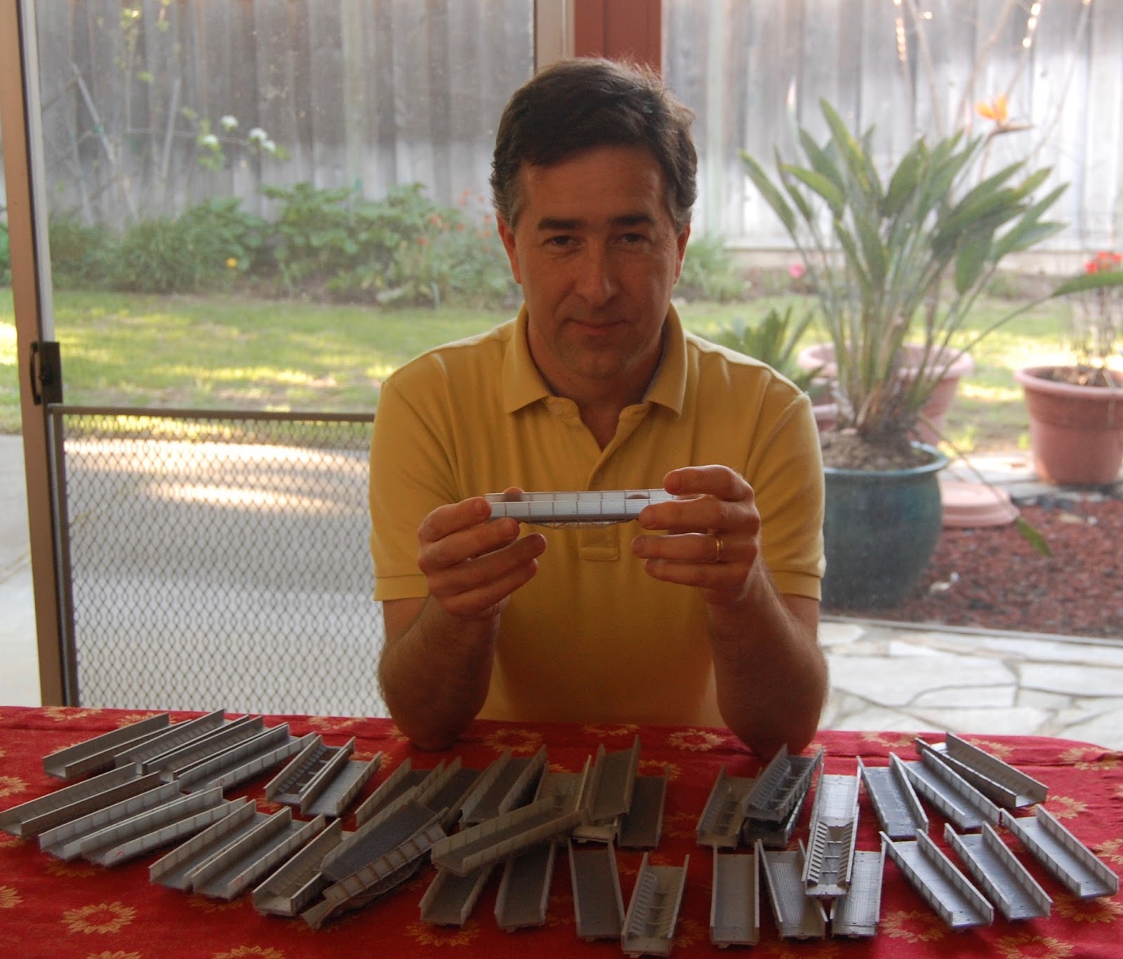
Author poses with some of the rejected prints. I'm ready to design a realistic wreck scene at the bottom of a canyon.

Failed prints also had a bigger cost than I'd imagined for both inspecting the models and repairing (if possible) any flaws. I'd expected gross failures - the model emerged from the printer with pieces missing. About 20% failed like that; the rest had other problems which required closer inspection: hard-to-see flaws in detail, hollowed-out posts, insufficiently cured cross-braces, sticky finish from insufficient rinsing, warping after printing, or rough surfaces because of printer problems. These sorts of flaws were painful because they required a lot of effort to look over the model, fix, and judge the model against previously-printed models; sometimes, they required changes in my process for making the cars. I made checklists to make sure I looked for all the common flaws. I made gauges to test if car ends bent out excessively.

Comparing models was a challenge. Most of my print runs were in small multiples (1-4 car bodies), so there were always differences between each run. Small runs meant it was hard for me to consider which models had significant flaws. I found it hard to remember what counted as a major flaw, and what was still worth shipping. I ended up running several print runs, then comparing all the models against each other to decide which were decent. Often, I pulled my pilot model or cars on my layout aside to remember where those models weren't perfect.

Photo documenting particular car, along with miniature form for tracking a car batch.

Problems with yield also made me much more systematic about how I was making the cars. I made lots of test prints to figure out orientation and what printed successfully or not successfully, testing whether I could actually mass-produce the kits. I also adjusted the design several times to add support structures to make sure models printed well, and tweaked the support structures so they were easy to cut off of the final model. Problems with warping models, parts breaking during cleanup, or other problems (sometimes caused by orientation, sometimes by printer malfunctions, sometimes from environment, sometimes from weaknesses in the design) always derailed things until I could track down a cause. I created jigs to keep certain areas from warping after printing. I kept paperwork - spreadsheets, diaries, photos of previous models, and paper forms tracking specific batches to remember what I’d done. I kept records of which run each car came from, and which run each buyer received.

Can I print models on demand efficiently?

I'd started with the idea that 3d printing would let me make things just as they were needed. I could have six or seven different designs ready, take an order for a mix of cars, then 3d print them all within a day or two. Rather than keeping stock and spending money on resin, I'd just wait for the orders to come in, print exactly what the buyer wanted, and mail them off.

The idea of printing on demand ended quickly. I found it was a lot more efficient to print a bunch of cars at a time, and then to do the assembly and boxing in an assembly line fashion. Yield problems were one of the reasons, but just assembling the bits for a kit - instructions, boxes, parts - took non-trivial time.

Similarly, I'd assumed that 3d printing would allow me to adjust designs quickly and iterate. This was somewhat true - I could update designs and documentation between runs, and often did. Some changes were transparent - changes in support structures or orientation didn’t affect the future model. Some involved operations of the final cars, such as adjusting coupler height. Other changes affected designs in small or large ways, such as correcting the model when I learned that the side door latches were only on every other door.

However, making changes every few models opened up new problems. If I updated a design, should I keep selling the old? Could I make sure a purchaser got multiple kits with identical details? Did the documentation match the specific car? For some changes (such as correcting the latches), I stopped selling the incorrect cars. To make sure purchasers got identical cars, I wrote batch numbers on the boxes, then checked records to make sure different batches had the same features. Changing the instructions frequently also increased my workload. Rather than print a couple hundred sets of instructions at Kinko’s, I was printing the instructions on my slow inkjet printer, and collating the pages myself.

Profitable?

So I can sell cars... but is it a potential side business?

The answer is "probably not", I think. Doing small runs is great for a hobby business and to satisfy a niche market, but the effort needed to do runs of less than a hundred kits always means it's going to be a wash, financially. I can recount a bit of my costs to help explain the problem.

First, price. I chose the ~$35 price point for my kits to be close to the typical price of a resin kit these days. I assumed I was going after the same sort of buyers as resin kits - modelers interested in precise prototypes, and with the willingness to build kits. I also wanted to make a prototype that could be built as a long string, just like the real cars, and so wanted to make sure the price would allow someone to build five or ten cars. I found a lot of my buyers were also die-hard Southern Pacific fans, often interested in otherwise-unavailable prototypes; I suspect those buyers were less price-sensitive. However, I suspect higher prices would make it harder for these folks to buy from an unknown manufacturer. (For contrast, go to Shapeways, and note the $170 Hart gondola built from a Canadian narrow gauge prototype. The modeler was certainly hoping to get his development costs back, but I suspect most modelers would flinch at the cost.)

For the first model I put on the market (the Hart gondola as originally built), I sold around 40 kits in the first couple months. I suspect I will sell a similar number of the "modern" Hart gondolas. I got these sales through only three ways: advertising on the Espee mailing list on Yahoo Groups, a very nice article in a well-known SP modeler's blog, and word of mouth. The blog post generated the vast majority of the sales, both because the readers included most serious SP fans, and because folks trusted the well-known modeler's opinion. There was a blurb in one of the online model railroad magazines, but it generated a small number of visits to the web pages.

If I was pushing these more, I might consider advertising in some of the historical association newsletters. Because the SP's W-50-3 Hart gondola was also used by the Union Pacific and Pacific Electric, another angle is to advertise explicitly to these communities. I'd also guess I could sell a fair number of kits at the Southern Pacific Historical and Technical Society meeting.

In terms of costs, resin costs, machine costs, and labor dominate. Each car took around $3.75 in resin and $3.00 to cover depreciation of the machine per print; increase those costs to account for prints that failed. Packaging cost around 65 cents for box and labels (not including labor to print and apply) Detail parts (stirrup steps, wire, brake wheel, chain) probably would have been around $4.50 each, which explains why I gave up on including these quickly. 0.010 wire was one of the larger costs; if I had an easy way to straighten and harden brass wire, it might have been reasonable to include these in the kits. I initially estimated I'd need about 15 minutes of labor for kits for all the work: making the prints, cleaning, finishing, and inspecting, packaging. In reality, it took a lot more effort, especially including the costs of handling prints that failed. At $20-30/hour for my time, that's way too pricey per car; to really turn this into a business, I'd need to be able to go from printed model to box quicker. I'm not including additional time - bookkeeping, keeping the 3d printer running, etc.

Keeping printer working was particularly challenging; when it was printing well, I could produce cars efficiently; when it was having problems, I was dead in the water for significant time. My Form One Plus printer is pretty amazing; although it's pricey ($3500), it's much more affordable than the commercial machines, fits in a home setting, and the resin is relatively inexpensive at 15 cents per cubic centimeter. However, the commercial printers have service folks who can be out in a day; the "prosumer" printer won't be that easy to get repaired, leading to a ton of downtime.

I had the Form One fail three times: once, one of the galvanometers went bad and messed up dimensions in one axis; that was an obvious failure deserving a replacement. The second printer died when it slowly stopped printing anything useful. It took about a month of back-and-forth with support before they replaced the machine. The third machine printed 37 great cars (out of 55 attempts) before it started curing the wrong sections. I'm suspecting that's caused by dirt on one of the mirrors; after I finish this post, I'll probably be spending a day getting the printer running again.

Could I have mass-produced models with narrow interest without the Form One? Perhaps. Others certainly have cut molds and injection-molded kits. For the cars I've done, I'm not sure there's enough demand to make cutting molds worthwhile. I also suspect designing a plastic kit for assembly is an immense amount of work. Some cars (like flat cars) perhaps would be better done as resin casting, but doing so requires me to learn a new trade. Finally, I could fall back to Shapeways if necessary. Shapeways price for just the body (not including any profit) would be around $70, raising my retail price significantly.

Best Models for 3d Printing

I think I had one really big advantage with the Hart convertible gondolas: they simply couldn't be made easily with other manufacturing techniques. Anything I produced was likely to be special to folks buying the kits.

I’ve found that my 3d printed models easily had details approaching the quality of injection molded or resin models, and certainly meet my standards for cars on my layout. The models always felt a bit “softer” than injection molded kits, with features often a little rounded rather than being extremely sharp. This was also true with Shapeways models printed on top-of-the-line printers. Though the Shapeways prints were a couple notches better than my "prosumer" (halfway between consumer and professional) 3d printer, the Shapeways prints were cleaner and more consistent. However, I could imagine some modelers would have been disappointed that the models weren’t “as good as” other techniques. If I’d sold a 3d-printed car that was easily done in plastic or cast resin - a boxcar or flat car, for instance - I could imagine some modelers being disappointed that models weren't any better than existing kits.

Luckily, I chose models that can’t easily be done in resin or injection molding - the truss structures on the Hart gondola just couldn’t be done in one piece in any other way. I think this was an important choice for me; my models got compared against either 1960’s craftsman kits, or against the fact that no alternative existed. I got several comments from buyers about how the cars were unlike anything else they’d seen. Their delight meant that folks weren’t comparing the models straight against a kit using other manufacturing techniques. Making a single-piece kit also gives me an advantage; 3d printing kept folks from having to do the fiddly assembly work required by plastic or resin kits.

Future plans

So what did I learn through all of this? Well, my kits show it's possible to make commercial models using a 3d printer like the Form One resin printer. If you're doing this for income, I'd say be very careful - the you really do need to sell hundreds of cars with many different designs to make decent money. Hiccups with the printer can also drive your income to zero, and can take weeks to solve. I suspect model railroad pioneers like Irv Athearn or the brothers who started Kadee were successful because they had skill at keeping their home-brew machinery and injection molding machines running at all costs, not by waiting for the injection molding machine repairman to show up. For a real test, try printing forty or fifty of the model you're intending to sell, and see if your printer (and your processes) can handle it. If you're going to seriously start producing models with a 3d printer, consider buying two so that you have both a backup and a way to swap parts and narrow down the causes of problems.

If you're a fan of a particular railroad and aren't too concerned about making a profit, then 3d printing special cars like this is great fun. I'd still suggest going after cars or details that can't easily be done by resin kit makers or injection molding, because it'll be easier to delight your buyers with something they can't get elsewhere. Definitely make the kits in a big run; make a guess about how many you may sell, and do all the printing and kit assembly at one time. You'll work faster, and you'll have less stress if the 3d printer stops working well.

Even if these models weren't profitable for me, it’s been a fun vanity project. I’d started the project because the material costs looked like a win ($3-$4 in resin, and maybe $3 a model to amortize the cost of the 3d printer). However, producing the models, packing, and shipping the models was a lot more work than I expected. Some of the time required might go down as I get more practice at producing the kits. However, other costs - such as cutting off support structures from printing, handling the models for drilling and tapping holes while the material is less brittle, curing the final model, and inspecting models - were really required by 3d printing and by the materials I'm using.

My future for 3d-printed kits is a little hazy; I'm starting a new day job soon, and that'll be taking my energy for a while. I'll continue to sell the existing stock of cars; when the stock runs out, I'm still undecided about whether to keep producing cars, or instead start selling the Hart gondolas on Shapeways. Either way, I suspect I'll still be doing a ton of projects on my Form One.

I’m still glad I’ve done these cars. I’ve justified the work by thinking of it as a fun project and as a contribution to the hobby. I’ve often described the process as similar to writing the book. There's not much profit for the work required, but I'm able to share details about a very interesting and unusual car with the Southern Pacific modeler community.


Thanks to the folks who have bought Dry Creek Models kits for their support and encouragement. Great thanks to Tom Dill for feedback on assembling an early model. Tom Dill and Joe D'Amato also photos of their completed models, which was a nice reminder of why I'd gone to all this effort. Tony Thompson introduced me to the term "aspirational" for model purchases done because the buyer got a thrill just thinking about building the kit. It's a great term explaining a pretty common way that all us hobbyists behave. Thanks to Jason Hill for insights into 3d printing and injection molding. Finally, thanks to the DCC Lunch crowd in the Bay Area who had to listen to me chattering about 3d printing and gondolas for too long.

Friday, March 11, 2016

Second Kit: "Modernized" Hart Convertible gondolas

If you liked the Hart convertible gondolas I've been making (and selling) recently, but found the cars too old-fashioned for your layout, then today might be your lucky day. I'm now making a "modernized" version of Southern Pacific's W-50-3 Hart Convertible gondola, suitable for model railroads from the 1920's to the 1950's.

As you've read in the past, Southern Pacific's W-50-3 ballast gondolas were neat cars. The cars, built in 1911, used a patented design from the Rodgers Ballast Car Co. to make them useful in many different kinds of maintenance-of-way service. This "Hart Convertible" design looked like a normal gondola, and could be used for hauling ties or other loose material. Open some doors in the gondola's bed, and you'd expose a hopper, ready to dump ballast between the tracks. Close the hopper doors and unlock side dump doors, and you could push dirt out of the gondolas onto the sides of the track. Close the side dump doors and remove the end bulkheads, and you could easily pull rail out of the car for track-laying.

By 1926, plans show that the SP started removing the side dump doors, replacing them with solid wood sheathing on each side of the car. This change also cut the capacity of the car, and also removed the locking mechanisms that held the side dump doors shut. The SP didn't remove the brackets on each post that held the side locking mechanisms - the brackets also supported steel rod holding the car posts to the frame that probably kept the sides square. As a result, the modified cars had odd, unused castings on each post of the car.

SP kept using the Hart gondolas into the 1950's. A hundred of the original five hundred cars were still on the roster by 1950. By 1955. all the W-50-3s were gone. I've heard stories of cars abandoned along the Cuesta Grade near San Luis Obispo, and trackside in the Oregon Cascades.

If you'd like one of these modern cars for your layout, check out the Dry Creek Models website for photos and ordering details.