Showing posts with label signals. Show all posts

Saturday, February 24, 2024

Getting Way Too Excited About Terminal Strips

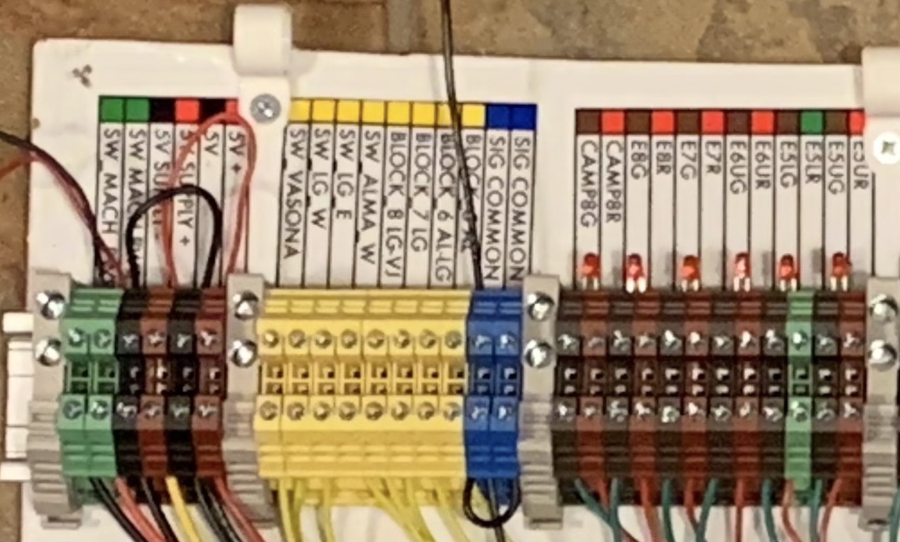
In my last post about replacing the Vasona Branch's signal controller, you might have spotted those odd terminal strips in the pictures of the new signal controller. These are the Dinkle modular terminal strips (the 2.5N size) intended for professional use on industrial controllers and electrical panels. As someone who grew up using the vintage Molex black terminal "barrier" strips from Radio Shack, the terminal strips definitely feel like I’m in a new century of wiring practice. The individual terminals in multiple colors clip together onto a DIN rail, a common mounting bracket for electrical equipment like controllers and circuit breakers.

I found them great for model railroads (as compared with the traditional terminal blocks) for a few reasons:

  • packs more terminals in the same space - about 3/16" per terminal
  • multiple colors so easy to identify terminals and polarity
  • inset test points for safer testing with voltmeter
  • supports adding jumpers for wire-free connections between strips, and two jumpers allowed on any terminal.
  • terminals are covered, so loose wire less likely to touch others.
  • able to reconfigure as wiring changes - possible to pop terminals out of the middle to change colors, or move end clamp blocks to add terminals.

Close-up of the Dinkle 2.5DN terminals showing how they're wired and attached. Terminals are 3/16" wide, wire is 22 gauge.

The price is a bit more than terminal strips from Amazon; they work out to about 30c a terminal compared to 12c a terminal for the classic terminal strips. (They're all a deal compared to $4 each at Radio Shack back in the 1980's!) The other challenge is that getting an assortment of colors requires buying a box of 100 terminals at a time - that’s $30. Getting a good assortment (red, black, green, yellow, blue, white, and brown) requires spending about the same as a plastic locomotive. You’ll also need some of the DIN rail, and some of the end clamp blocks for securing a row of terminals. (For our low voltage uses, you don’t need the thin plastic endcaps to cover the last terminal in a row.) I’m planning on using all I need then selling off spare terminals to someone else if I've got enough unused terminals. I could also imagine having a group of modelers team up and share an assortment.

Jumper with every other pin cut. With these, I could line up a row of alternating green and white terminals for the different switch machine power feeds, then use two jumper barss to connect all to power coming in from a single pair of terminals.

The colored terminals are particularly nice for documenting the wiring. I use different colors for DCC supply vs terminals going out to the tracks (red/white vs red/black), and could color code for signals easily (red/brown and green/brown terminals for “upper” and “lower” signal lights at same location. Sets of terminals can be connected together using jumper bars that fit into the top (and don't interfere with the screw terminals.) 10 terminal jumper bars are available, and can be cut shorter to gang several adjacent terminals together. For the switch motor power, I ended up cutting every other pin from a pair of the jumper bars so that I could feed in the two wires for power to one set of terminals, and have power distributed to all the other pairs simultaneously.

The color coding and labeling also helps me double-check wiring and remember how things are connected years later. When I rewired my DCC track connections using the new terminal strips, I realized I’d mis-connected power from multiple boosters to different stretches of track, probably because I lost track of which terminals were for which section of the railroad. That mistake caused me to melt at least one locomotive when it shorted against a switch but was still getting power from a different booster.

Drawbacks? I needed to use a smaller screwdriver to fit the protected holes for the screw terminals - I couldn’t grab any random home repair screwdriver to turn huge screw heads. The terminals also bent a little bit when pulled by larger wires like solid 12 gauge DCC buses, but work fine for smaller wiring.

One of the rewired panels. It's much easier to understand now!

I’m slowly going around the layout, cleaning up wiring, adding labels, and adding the new terminal strips. I’m very, very happy with these - the terminal strips make it easier for me to understand the wiring even years after I’ve done it, and they make the underside of the layout look neat and organized. I suspect I'll love the terminal strips even more in ten years when I need to figure out a rewiring I did in the distant past.


If you're interested in checking these terminal strips out: I got my Dinkle terminal strip parts from Amazon.com - search for "Dinkle 2.5N". Some sellers offer the components - separate purchases for boxes of 100 of each color terminal, for the end brackets which hold the terminals in place, the DIN rail, and the jumpers. Others offer assortments of 20 terminals of specific colors for common electrical projects such as solar panel controllers. The little assortment was a good way for me to decide the terminal strips were for me. I cut my initial cost when buying full boxes of connectors by just getting a few colors of terminals that I needed for some specific tasks such as re-wiring switch machine power. (I was using just green, white, and yellow for wiring connected to the switch machines.) I later got boxes of the other terminal colors as I rewired areas with other wire colors.

You can also see the terminal strips in use on the layout - the Vasona Branch will be open for tours at the NMRA Pacific Coast Region's 2024 Convention April 24-28, 2024 in San Jose.

Friday, February 23, 2024

Big Changes At Signal Gulch

Semaphores at the east end of Glenwood siding.

When is a model railroad “done”? Some might say it’s when it’s complete - when every scene is detailed and when the trains are running well. Some might say that a model railroad is always being changed, so it’s only “done” when it’s being torn down. I’ll throw out another option - our model railroad is “done” when we’ve confirmed that it’s the right design, when we’ve built enough to know “this is what it’s going to stay like”, and when we’re satisfied with the condition. One easy way to know when we’re satisfied is when we move from building new stuff to having to make big infrastructure changes - replacing a command control system, or changing control panels, or fixing other normally-invisible bits of the layout. If we’ve decided to do some wholesale replacement of some invisible aspect of the layout, that must mean the layout’s lasted long enough for us to need to do big repairs and that we’re happy enough with the layout to do the improvement instead of tearing down and starting a new one.

In my case, replacing the signal system suggests that I’ve done pretty good with this layout.

One of the pain points for my Vasona Branch layout over the last few years has been the signaling system. The real Los Gatos - Santa Cruz branch had automatic block signals (ABS) installed when the line was reconstructed after the 1906 earthquake. (Read Carsten Lundsten’s explanation of SP’s ABS signals here to learn what automatic block signals mean, and how the SP operated them.) The SP assumed the Los Gatos-Santa Cruz line was going to need increased capacity for future San Francisco - Santa Cruz traffic. As they upgraded the line from narrow gauge to standard gauge, they also added the automatic signals to minimize the effort of running trains over the mountains. In the narrow gauge days, keeping two trains off the same track required staffs and other physical tokens, or required explicit train orders to carefully control movements. Having multiple trains follow each other in the same direction was tedious and slow. The automatic block signals got rid of some of this work, allowing railroad crews to know the track ahead was safe to occupy. Note that ABS signals only provide protection, rather than authority. A green signal means that the track ahead is clear, not that your train is allowed to occupy that track. Those train order operators at the stations along the line are still needed to let trains know when they're safe to go.

On the model, the signaling system consists of a bunch of signals placed at intervals along the track, and a signal controller hidden underneath the layout. The controller keeps track of which tracks are occupied using detector circuits and notes which switches might be thrown away from the main line, and sets the ABS signals accordingly. Soon after I’d laid the track on the upper level of the Vasona Branch, I bought a pair of signal controllers - SIC24 (“Signal and Indicator Controllers”) from Team Digital. The SIC24 is a small circuit board with a programmable chip on it; using a DCC programmer (or LocoNet), I could program in signal logic so that if a particular track detector indicated a train was present, or if the switch on either end of a single track was thrown wrong, a signal would go red. The Team Digital boards could also be connected together so that an input on one board could affect a signal output on the other. I used two boards for the needed 16 inputs and 48 outputs. All the signals were within about 10 feet of the SIC24 boards, so I connected all the signals with twisted-pair code 26 phone wire - no need for scattering electronics around the layout.

Old signal controller. Not my best work, but it worked for more than ten years.

The photos shows one of the two SIC24 boards, and the phone cable providing the connection to the other board. This wasn't my neatest job, but it worked. You can see the signal power (large green wires with suitcase connector taps), inputs are yellow wires to the left, and signals are green/white and red/white wires below. I'd realized it was easier to put resistors on all the inputs and outputs here, so they're soldered onto the wires leading to the terminal strips. The odd shape of the plywood is because it's a scrap left over from cutting roadbed for curved track. I was unsure enough about whether the signals would be interesting that I didn't bother to build for good appearances.

The SIC24 boards generally worked well. They “just worked” when the power came on, they had sufficient smarts to run ABS, they were configurable enough to handle a couple of non-standard layouts on the place, and they didn’t require having a computer in the garage with the layout. Over the years, though, the SIC24 boards did start showing problems. One problem is that there’s no way to debug what’s going on; if the indications weren’t making sense, it was hard to diagnose exactly what was happening without attaching a voltmeter to inputs and trying to remember how I’d programmed the boards several years before. I ended up building a little circuit using an Arduino microcontroller board that could listen to the two cards talking and show on a tiny screen which inputs were changing, but that was clunky to use, requiring me to crouch under the layout, plug in the device, and look at a tiny 2" screen to understand what inputs were seen. Over the years, there were also times where it seemed that bits of the signal programming were getting lost. Because I don’t have any Digitrax equipment, reprogramming the cards meant detaching them from the layout, carrying them to a programming track, and attempting to reprogram the whole card from JMRI. I’d then have to reattach the card and see whether the change took - whether the signals now worked correctly. If they didn’t, I had to guess whether I’d mis-programmed the card or if the card was having problems. The several minute delay between making a change and seeing if it worked wasn’t fun, and caused me to give up on several bad signal problem.

I’d finally gotten frustrated enough to decide to replace the fifteen year old signal system a couple years ago. There’s plenty of choices out there, both commercial and home-made. The current NMRA Layout Command Control (LCC) standard defines how to build interoperable signal systems without a central computer. The LCC boards are expected to be scattered around the layout near the signals, then connected via a common bus to communicate. RR-CirKits is selling its Signal LCC and Tower LCC boards that work a lot like the SIC24s I’m currently using. However, they’ve still got the problem that debugging what’s going on requires a computer in the garage, increasing the work required for debugging. It also required me to get up to speed on a new technology, and I’d found some of the online manuals cryptic. Another possibility would be to go in the direction of Bruce Chubb’s centralized CMRI (Computer Model Railroad Interface). CMRI systems have a computer program control the signals, and defines how the different boards scattered under the layout all talk to the central computer.

Both of these are a bit of overkill for me. CMRI seems intended a larger and more complex layout than I have, and has expectations about having a desktop computer present running specific software. LCC has the decentralized and hardcoded logic that I liked from the SIC24, but has similar problems with monitoring and debugging problems, and required me to come up to speed on how LCC worked.

Unfortunately, my day job is as a software engineer, and so whenever I come across “do I buy something to make this happen, or do I just roll my own?”, I’ll often decide to go and build it. That’s often seen as a wasteful choice - why rebuild something that’s already available on the open market? However, for a small home layout, building my own makes more sense. I’ll know the design, know how to debug it when it breaks, and won’t be forced to do upgrades.

In a perfect world, I’d have a tiny Linux computer under the layout controlling the signals, I’d be able to write my own code for controlling the signals, and I’d be able to run a little web server to show the current status of the signals. That’s not a hard thing to do these days; I can buy a Raspberry Pi single board computer for $50. The only question was how to control the signals.

To keep my “no computers in the garage” rule, I chose to build from the Raspberry Pi. This is a little computer that’s the size of a deck of cards, but runs the UNIX operating system and can be logged into and programmed just like a larger computer. It’s easy to hide away, starts up within a minute, and is infinitely configurable. To handle the inputs from sensors on the layout and to power the LEDs for the signals, I chose Model Railroad Control System’s IOX32 boards, small boards with 32 inputs or outputs that can connect to a computer. The IOX boards are built for CMRI based layouts, but the way they talk to the computer, using the standard I2C wiring that lets different devices in a single computer talk, means they can be connected to the Raspberry Pi directly. I ended up getting a Raspberry Pi “hat” - an add-on circuit board that attaches to an expansion port on the Raspberry Pi - to provide the I2C connections. Finally, to help debugging, I bought a small two line display from one of the online electronics companies. This board also talks to the Raspberry Pi using I2C, and can be told to display short messages to help debugging.

This photo shows the new signal controller mounted on plywood. The terminal strips for power, inputs, and outputs is at the top. The Raspberry Pi is the box with the red board in the lower left. The IOX32 boards are to the right of the Raspberry Pi, and the display and 5 volt voltage converter for the IOX32s is to the left of the Raspberry Pi. The crossing wires were needed to match the layout of the terminals on the old and new boards.

As can be seen from the photos, the signal system has a lot of wires going in and out. In order to make the replacement go smoothly, I set up the new system on a plywood board with terminal strips for all the connections, then wrote the software to control the signals and tested it on the bench. This also helped me confirm that the IOX32s could correctly drive the LEDs I use for signaling. More importantly, I made sure the terminal strips roughly matched the layout of the existing board so I could disconnect the old board, detach the old wires, put in the new board with controller, and reattach. I also made a few very good choices to help installation - painting the board with the electronics white for easier viewing under the dark layout, printing up very clear labels indicating the purpose of each terminal, and making sure I had good terminal strips for attaching the connections.

New signal controller in use. LEDs are for signals that aren't yet connected - I've added LEDs on the terminal strip to check their state.

Finally, I took a deep breath, detached and marked the existing cables, pulled out the old controller, and put in the new one. The new system required a bunch of manual work - soldering extensions on too-short wires, changing how some of the detector circuits were powered to ensure a safe common ground between equipment around the layout, and slowly reattached and tested that the signals still worked. This all happened within a couple long days, but it went well with no surprises.

The Raspberry Pi did make it easier to debug. Checking out the existing signals, I found one of my long-lived problems was an incorrectly-attached input for one of the switch positions. I also found some incorrect assumptions in my signal programming, and with a few lines of programming changes was able to get the signals working like the real thing. Debugging is, for now, looking at text logs spewing from a computer program, but I’m looking forward to writing some code to show the layout state on a web page next. I even added a lamp test action at start that flashes all the signals - this makes it easy to double-check that all LEDs are connected and are working.

The biggest drawbacks? The Raspberry Pi does have more complexity. It's a full fledged computer with a boot disk (stored in these modern times on a MicroSD flash memory card.) If the boot drive gets corrupted, then the signals won't work. I’ll need to keep a backup SD card just in case things break.

I must be happy with the Vasona Branch, because I’ve done a big wholesale replacement of the signal system. It took several weeks to get the home-brewed signal controller ready, but all the planning and preparation made swapping the old for the new an incredibly pleasant exercise. I now have much better control over the signal systems, can better understand why it misbehaves, and can quickly fix it so it works correctly in a prototype manner. There’s still lots to do before the layout is fully scenicked, Being willing to do this wholesale fix, though, reminds me how happy I am with the current layout, and how far I’ve come.

Wednesday, August 19, 2020

Bring in the Photographers!

Full disclosure: all photos here are mine documenting the weekend, not the shots the pro guys made.

Well, that was an interesting weekend. As part of preparations for the NMRA 2021 National Convention, Rails by the Bay, I got a chance to get my layout photographed for articles about the convention. Model railroading’s a lone wolf hobby for me, so I’ve never had anyone else doing serious photos of the layout. I instead got to sit and see how others thought of my layout, and how they worked to get great photos. I also changed a bit how I think about the layout as a result.

So let’s talk about aiming for good photos in terms of planning, preparation, and the photos.

If model railroading taught me anything, it taught me project management. Building a model railroad always involves a long effort to build something significant: deciding what to build, sequencing all the work, rolling with the voluntary and involuntary changes, and ending up with a completed model railroad. I found out about the photo sessions at the beginning of the year, and realized I had some time to finish a couple scenes that had been lingering. I used my usual tricks for deciding what to figure out what to do: fix what annoyed me the most, and fix what I was in the mood for.

Two projects won. First, long suffering Glenwood’s scenery finally got redone. I’ve written a bit about that previously, but to recap: it has the potential for an eye catching scene, the prototypical curve makes it easy to stage reproductions of historical photos, and who doesn’t like model trains in mountain scenery? I’d first ripped out the old scenery and fixed some notoriously unreliable trackage near and in the summit tunnel. I redid the hills and Glenwood Highway to better match the terrain. I then covered the area in trees. Normally, I try to build trees from Woodland Scenics kits, but this time I bought from Grand Central Gems at a recent train show, and had a redwood forest ready in days. I ballasted track, detailed the former turntable pit, and built a quick reproduction of the Glenwood station from styrene. (I’ll talk more about the station another time.). Glenwood needed a water tank, so I quickly grabbed one of the venerable Atlas kits and put it into service.

By the time the scene was done, COVID-19 had hit and the original deadline for the work - the Prorail operating event had been cancelled. We rescheduled the photoshoot for August, which gave me motivation for another project. This time, I decided to go after downtown Campbell. The Campbell scene’s always been a focal point for the layout, but the scenery and structures have been half-done for years. I’d built the station model years ago and scenicked the station side of the tracks. However, the opposite side of the tracks was still temporary buildings and little scenery. That included downtown Campbell, Sunsweet, the Hyde Cannery, and Ainsley cannery. This area provided some great scenes - space to photograph long trains, switching action, and lots of canneries. I started on a big push a couple months back to redo everything. For downtown Campbell, I redid the road and building bases, and started trying to pull all together.

I’d already done four of the five buildings for the downtown Campbell Ave., but had held off on the most impressive of the group - the Growers National Bank building that had been downgraded to the local movie theater by the 1930’s. (The building still exists in 2020, though I think they're still fighting about whether to allow it to become a night club.) I’d made a couple attempts at starting the bank, finding a suitably regal plastic model, but the space on the layout was tiny - only about twenty feet wide - and the model wouldn’t fit. Unable to do things perfectly, I just gave up and decided I’d do the model another day.

That day finally came as I cleaned up Campbell Ave. I tossed out my ideas of a "perfect" model and decided to just start building and see what turned up. Like the Dutch signal box, I finally got annoyed enough to just start building. Like that model, I used styrene sheet primarily. Again, large dimension styrene rod worked really well - the 2 foot inset for the doorway was simply 0.250 styrene bar, simplifying the construction. A leftover door and window served for entry. I used brick sheet for the walls; the detail along the roofline were strips of board-and-batten siding standing in for carved stone. I crafted the theater sign from styrene sheet. I would have liked to 3d print it to get the lettering perfect, but my older SketchUp software doesn’t seem to want to render 3d characters.

<

Campbell Theater

Bank of Camera Close-up

With Campbell Ave. in, and the road glued down, my next project was fixing the Ainsley Cannery. The Ainsley site’s had a posterboard mockup ever since the layout was built; I still remember Byron Henderson complimenting me during an early operating session because the freight door spacing matched my 40 foot freight cars. Back in 2006, I had a great solution for the cannery - I’d found a YesterYear Models “fruit packing house” - actually a former Sunkist packing house from Riverside, California. The box has been gathering dust ever since as I waited for just the right inspiration to use it for the cannery. This was finally the time to pull the kit out of storage. The overall shape of the buildings are similar - both were a row of wooden barn-like buildings. Like Sunkist, the Ainsley cannery had an office in the end closes to Campbell Ave, and a loading dock dominating the front of the building. As a result, the rough arrangements of windows and doors would work fine as-is. One big difference was that Sunkist’s building had two joined wooden sheds, while the Ainsley cannery had two corrugated iron sheds and two wooden sheds in a line; historic accuracy went out the window in order to get a "good enough" model done as I ignored the corrugated iron sheds. I ended up cutting the Sunkist building in half, and using both ends side-to-side, and ignoring the different materials in the various sheds.

The Drew Cannery, formerly Ainsley

Preparation

All that major work took me up to last week. However, I still hadn’t done much of the preparation work, so I kicked into a big cleanup mode. Our photographers recommended doing a serious cleaning so extraneous dust or debris visible on photos. I also got rid of all the little problems I'd ignored over the years. Some was operating session damage - having folks handle models is always going to trigger a bit of damage. I fixed broken signs and bumped trees, repaired damaged cars, fixed scratched paint or bent grab irons, and filled in ballast holes triggered by past cleanups. I dusted off a set of “good cars”, and stashed away cars that were the wrong era or had visible damage. I fixed long-lingering projects -holes in scenery I’d never addressed, half done patches, and rough surfaces. Some were really quick - I’d never patched scenery when I’d rearranged the Wrights tunnel. Some were larger, such as finishing half-done spackling in the Meridian Road scene.

Most of the preparation work was the same I’d do for an operating session. For operating sessions, I’d also be worrying about reliability, cleaning car and locomotive wheels, testing that engines were working fine, testing couplers and trucks. None of that sort of work mattered much here - the trains would be stationary in the pictures. I was pretty relieved not to be doing a serious cleaning. Serious cleaning's always a huge time sink, and I always want to over-prepare - I’m always worried before operating sessions whether a balky engine or dirty track will make for an unpleasant operating experience.

Another great advantage of photos is that locomotives don't need to run well. The real Vasona Branch likely had small 0-6-0s switching the canneries. On my model, larger 2-8-0 locomotives instead get the job. I really like the little 0-6-0s, but can never use them for operations. They tend to be balky runners and stall way too easily. When operators are focusing on how to solve a switching puzzle, the last thing they want to do is deal with a stalling or broken locomotive; it interrupts the illusion of working on the railroad, and usually ends up with waiting for the layout owner to clean track, fix the engine, or provide another locomotive. With photos, however, a balky or stationary locomotive isn't a bad thing, for the trains don't need to move in a good photograph. I cleaned one of the rarely-used 0-6-0s, and it got a few chances to be on center stage. To be fair, it's still good to have working locomotives if only to quickly pull cars around the layout to a new photo site, but a photo session removes a lot of the worry of mechanical problems.

While some tasks such as wheel-cleaning and locomotive tuning don’t make sense for photos, other tasks not needed before operating sessions were needed. I’m usually a bit hesitant about putting detail on the layout. It’ll often get damaged during operating sessions. I’ve hoarded some details so they’re available when I need to fill in a scene to be photographed. The layout hasn’t always been at a stage where it’s ready for detail.

But hey, if the layout’s going to get photographed for real, this is the time for all that detail. I pulled out my box of various details I’ve hoarded during my time in the hobby. Every Woodland Scenics pallet I’d ever gotten from a detail kit went on the layout. Extra parts from a Fine Scales Miniature kit that couldn’t handle more crowding. All the 3d printed boxes, bags, lugs, and can stacks I’d printed went on any available loading dock. I plopped down figures where they were appropriate. I took a pair of 3d printed flagmans shanties and phone booths and placed them wherever they’d fit. I took the large fruit bins from the YesterYear kit and made a box yard for Del Monte #3, just as can be seen in photographs.

I also put in a bunch of telegraph poles along the right-of-way. I’ve had these on the layout before; they tend to get a lot of abuse, but they’re eye-catching. This time, I spent an evening assembling and painting a set of telegraph and power poles from Rix Products and Atlas. I also painted them a bit more carefully than before. Previously, I’d just painted the telegraph poles a quick brown and added a bit of green for insulators. This time, I made the colors stronger than last time - darker posts, silvery supports, green insulators. In place on the layout, they really catch the eye. For the Meridian Road scene, I also made a point of doing a power/telephone line paralleling the road which helps to make the scene even more realistic.

And thanks to some crazy times at work, I crammed a bunch of this work into the last week, and into a mad three days. We were also in the middle of a serious heat wave here in San Jose, so the hardest part was avoiding heat stroke in the garage, but on the plus side the matte medium dried really, really fast. The roof of the Ainsley cannery got painted just as soon as the glue holding the paper tarpaper on appeared to stick. I laid ballast in a bunch of places that had never been ballasted, and managed to paint and clean the rail in time. I decorated new scenes - bushes hiding a farmhouse along Meridian Ave, a path to the bathroom around the edge of the Rio Grande gas station, and a row of posts to keep parked cars away from the Campbell depot. I was bouncing back and forth between touching up scenery, weathering cars, and touching up structures. When I was checking old photos to get the sign on the Ainsley cannery declaring it to now be the Drew Cannery, I noticed a speed limit sign, and quickly printed up several of those to control the HO scofflaws. I was still touching up ballast and fabricating a set of stairs for the Glenwood depot a half hour before the photo session.

I never completely believed those model railroad magazine articles where someone built a well-detailed layout in a year or two. I couldn't imagine they had time to decide on models, do the construction necessary, or add the details. This week's mad rush convinced me it was possible. All I needed was some definite ideas of what should be built, an urgent deadline, a bit of wiggle-room on what counted as "good enough", some well-stocked supplies, and way too much manic energy.

And the Photographers Arrive

Dan and Doug, the photographers, were spending several days just photographing layouts in the Bay Area. They've also done this before for previous conventions and other layouts, and came fully prepared. Although I've read about model photography in magazines, this was my first chance to see pros in action.

They came prepared: lights, power cords, and various secret photographer paraphenalia. The extension cords helped when the breaker blew on the garage circuit - our 1960's house wasn't designed for this kind of model railroad lighting, and we quickly found another circuit to share the load.

Dan also had lots of cool tricks so he could get into the scene with his SLR - mirrors to capture scenes the camera couldn't reach, beanbags to hold the camera steady on the layout, high tripod for the upper level photos.

And they took photos different from me, too. Some of that was expected: they visited the Vasona Branch for only a couple hours, so they were very careful to make their plan of shots, then slowly move around the layout to hit each.

Big difference number one from my attempts at model photography: they bring in lots of light. The Vasona Branch has a mix of lighting: the garage lights are cool white fluorescent strips, but I've got various cool white LEDs and warm white fluorescent fixtures lighting the lower deck. I'll usually just use the existing lighting when I take photos; if I'm really taking care, I might borrow a couple bright lights from one source or another. As a result, my photos often have weird colors if a scene has a mix of LED and fluorescent lights. Dan and Doug used two or three photo lamps. Their lights quickly overpower any layout lighting. They also didn't seem to worry about the narrow space between decks - bounce light off objects was enough to light the scene. Their biggest concern seemed to be getting the scene evenly lit, and avoiding shadows on the backdrop. In places where they couldn't get lights, they assumed they could photoshop in some sky into the black background of the garage door.

Dan and Doug use mirrors and a hand-held photo light to capture a train approaching Alma station.

Big difference number 2: The big surprises for me was just seeing what caught their attention. I haven't seen their photos yet, but they understandably looked for interactions between trains and the world. Signals were a common tool to add some action, as were road crossings. My best guess is that model photos need the extra busy-ness and action, and really need some focal point other than the train. The Vasona Branch's semaphore signals were common places for photos. (That was also true on the prototype; one real photo that inspired me is a 1920 photo of a passenger train coming into Glenwood. That photographer, like Dan, made sure to catch the train as it "split the semaphores".

I also heard a bunch of interest about the farmhouse and orchard sitting in the blob where the tracks turn from San Jose to Campbell. This scene's always been half done and cluttered - details not glued down, ground not quite sloping correctly, the orchard too small to be realistic. I'd done a big cleanup of the scene in preparation for the photos - pulled out details, removed structures, and generally made it innocuous. But interest kept drifting back towards the farmhouse and barn. I'd started thinking about details as I was doing cleanup; I'd added a hedge to protect the farmhouse from the busier road. But the interest makes me think I should more seriously plan the scene out.

Dan and Doug also focused on the large details - freight cars and car models - rather than smaller details - not surprising because of the short time. They did spot one broken crossbuck that would have detracted from the scene; we pulled it out.

And that was pretty much it; they got ten good photos, and moved onto the next layout. I got to stare at the layout for a while; it's always fun to see the layout when it's been cleaned up for an open house or an operating session, and doubly-good when all the usual clutter in the garage has been relocated. Even though I'd crammed a bunch to get the layout in shape, I was still excited enough at seeing the layout in good shape that I finished off a couple projects that hadn't been done in time, replacing a remaining broken telephone pole, putting in some gravel around the Ainsley cannery, and fixing up the famous black walnut tree that sat at the start of Campbell Ave.

What did the photos show? I've seen the first photos, and they're great - Dan uses Helicon to combine photos taken at different focal lengths to get more depth of field. Looking at the photos, I see a few things to do differently.

  • I'm vertically challenged. In a few of the photos, it's obvious I've been less than good at making sure everything's standing up straight. They're close, but as soon as several objects are in a photo: semaphores, building, water tank, telephone poles - it's obvious each has a slightly different idea what "up" is. I'll need to work on this, both ongoing, and fixing the more obvious offenders before I next take photos.
  • Prepare for the story. I'd made sure to have cars set up in sample trains, but hadn't been good about choosing cars or trains to illustrate themes I'd want in an article about the layout. For example, large industries and lots of indistinguishable red boxcars is a big part of my layout, but I neglected to have a switcher ready at Plant 51, and also didn't make sure that the cars there were the uninteresting ones. I need to sketch out the story I want to tell beforehand, and share it with the folks doing photography.

What's next? The layout's clean and in good shape, and I'm excited to do some more building. Finishing Campbell is an obvious next step: the Hyde Cannery buildings are screaming out to be build. I'd held off on building the Campbell Theater and Ainsley Cannery because I wanted to make sure I did them right. However, my quick-and-dirty building rush seemed to work with these. Maybe I should just go build Hyde and see what happens?

The orchard scene's another obvious project.

Once both of those are done, there's obvious holes to fill. One advantage of cleaning the layout was that I got rid of all the building placed on the layout "temporarily" for lack of better space - a couple of farmhouses that never found locations, a drive-in market built for fun, a bunch of cars that needed repair. Now that the layout's opened up, I'm reminded that the area between Campbell and Vasona Junction is still completely empty. The Del Monte Plant #3 property's also still occupied only by foamcore buildings. There's also a stretch of bare plaster up on the upper deck near Alma. I'll need to take a pass on any of these scenes going forward.

If the last week's any indication, I know how to get those scenes done quickly: lock down my idea of the scene, build something that's "good enough" rather than waiting for perfection, and pull a bunch of all-nighters during a heat-wave.

Sunday, January 6, 2019

Building an Interlocking Machine For West San Jose Tower

As I’ve mentioned before, I like model railroading as a hobby because of the mix of projects I can do. I’ve got a friend who’s big into wargaming figures. His photos of some of his painted miniatures shows great work, but I always wonder “what does he do when he doesn’t want to paint?” Luckily, I’ve got no such problem; when I'm tired of one kind of project, I move on to another. Lots of projects go unfinished because I’m not quite in the mindset to spend time on them. Some times the project just gets delayed, and sometimes it gets rethought. I’ll switch and do something else for a while, and eventually I’ll come back. Maybe I’ll do the project as I originally conceived it; other times, I’ll throw my old ideas away and go in a completely different direction.

Take the Western Pacific crossing on my layout, for example. The WP crossing was a key part of my track plan, not because it was an active part of switching the canneries, but because it both helped set the location, and because it tied my railroad to the larger world. I had plans years ago for how I wanted to build it, but those plans never worked out. A while back, I rethought what I was going… and ended up with a new plan that sounds like much more fun.

The Crossing as Model

The crossing of the Western Pacific and Southern Pacific tracks in West San Jose isn’t much to see - just a set of tracks crossing between the Del Monte cannery and the Standard Oil spur. There’s an interchange track that gets a couple cars switched every operating session. I built a model of the WP’s 1920’s era switch tower years back, and I keep having ideas of putting the Virden Cannery next to the tracks, just like in real life. However, for the operating crews, there’s just not much there. Littering freight cars across the crossing when switching Del Monte is quite a common occurrence, and would have infuriated the real tower man for the Western Pacific Railroad on the real railroad.

I’d had ideas to make crews better respect the crossing. Somewhere around here, there’s an Arduino with a sound card to control some animation. It would play a soundtrack occasionally - a factory whistle, some cars going by, a far away whistle, and finally the sound of a WP train approaching. Some nearby signals would change to red (to announce the arrival of the train), and LEDs in the roadbed would flash as the phantom train passed. If that wouldn’t keep crews from blocking the tracks, nothing would.

The project that didn't work out.

The plans never quite worked out; I didn’t have a place for the speakers and was never happy with the soundtrack. The idea of making the crossing obvious and important during operating sessions did linger.

History of the WP Crossing

When the Western Pacific was built in the 1910’s, the Southern Pacific already had tracks in all the obvious locations around the Santa Clara Valley. The potential business from San Jose’s fruit industry encouraged the railroad to find a way to get past the SP’s tracks. The WP’s line from Fremont and Niles to San Jose had to parallel the SP for much of its length, then swing far south of San Jose only to approach the city from the south. The route required crossings at Niles Junction, at the crossing of the SP’s Coast Line at Valbrick, and a final crossing of the San Jose - Los Gatos branch at West San Jose.

The tower - West San Jose to SP, and Tower 17 to the WP, was built in 1922. The railroad signalling trade rag commented on the construction: a Saxby and Farmer interlocking machine controlled the semaphores, with 20 levers controlling signals and switches. The crossing was quite substantial, with WP’s branch line crossing the SP’s main line and two drill tracks right in the middle of the cannery area. Like all railroad towers, the second railroad to arrive at a place paid for it all - the track crossing, the tower, and staffing the tower. The WP never got the traffic it expected from the San Jose branch, and had little interest in staffing the tower on an unused branch line. By 1938, the tower was out of use. In later years, WP trains had to stop and check the SP wasn’t coming before dashing across.

James Barriger got a decent photo of the area around the tower in the 1930’s, capturing an SP switcher right behind the Virden Cannery. Although he didn’t capture the tower, he did show the trenches for pipe rods controlling derails on the drill tracks.

The Interlocking

On a railroad, a switch tower is a manned location that controls where several tracks come together, and where the track, switches, and signals are controlled to ensure safety and minimal delays. There’s usually a person present; he sets switches and signals to allow trains to safely move through the section of track based on train schedules, dispatcher orders, and the arrival of trains. Controlling those tracks is often done by an “interlocking machine” - a mechanical computer that ensures only non-conflicting routes can be set up through the stretch of track it controls. Interlocking machines usually have levers that control switches and signals, one lever per device. For the WP crossing, that means that the signals, switches, and derails can be arranged to let an SP train to cross the WP tracks, or allow a WP train to cross the SP tracks, but not both. (It also enforces safe order - the tower man can’t set a signal to green unless the switches and derails on the through route are set correctly, and derails on the crossing track are locked down.) Interlocking machines use a set of sliding bars connected to multiple levers to ensure that if lever A is thrown, lever B cannot be thrown.

As mentioned, the WP tower’s interlocking machine had twenty levers - were there really that many things to control? From various sources, we can guess what the 20 levers in the Saxby and Farmer machine controlled. The Barriger photograph shows piping for derails, suggesting all the tracks had devices to stop a runaway car on a track that wasn’t expecting a train. Railroad valuation map shows that the SP had distant (one mile before) and nearby signals closer to the crossing. Track diagrams show one mainline track and two drill tracks on the SP to handle switching the canneries in the area. One likely guess at the purpose of the levers would be one derail, one local signal, and one distant signal on the SP and WP main tracks in each direction (3 * 4 = 12 levers) + a signal and derail on each SP drill track in each direction (2 * 4 = 8) for a total of 20 levers - just what the trade rag says.

Locking bars, tappets, and tappet blades on the interlocking machine at Santa Clara tower. Chuck's photo.

So it would be neat if I could actually model the interlocking machinery, and give my operators an appreciation for everything involved with the tower - the rules about how train crews got permission to cross the diamond, the need to communicate to the tower man where they wanted to go, and the actions the tower man needed to do to line up the crossing. That means I need to build an interlocking machine - not a standard kit at my hobby shop. I’ve seen articles on how to make an interlocking. Model Railroader had a set of articles by Paul Larson and Gorden Odegard in the January-June 1961 issues of Model Railroader, but it wasn’t quite a step-by-step project, and the suggestion that the authors needed to build a wooden mock-up beforehand to test out the logic suggested it wasn’t a project for the faint-hearted.

Building a Modratec Interlocking Machine

Luckily, there’s folks who can help. Modratec, in Australia, sells kits for making a working interlocking. The price isn’t quite an impulse buy - about US$225 for 12 levers and electrical contacts, but it’s a pretty great little kit. To get an interlocking kit, you download their SigScribe4 software for setting up the constraints, define out how you want the levers to work, then mail off the interlocking details. You’ll get a kit back - all machined and ready to be bolted together, with a bit of metalwork to set the locking machinery to match your intent. I’d been considering this kit for a few years; I’d tried a couple times to get started, but never quite got it. A couple years back, I finally took the time to understand the software well enough to describe West San Jose Tower. The interlocking turned out really nice, and gave me a much better understanding of how real interlocking machines work.

Designing the Interlocking

The biggest challenge was just getting the interlocking designed. It took me several tries over a couple years to figure out the SigScribe software to get a working interlocking. Running through the tutorials multiple times helped. Once I understood the software, designing a new interlocking for my Market Street layout took only an hour. Don’t be surprised if it feels cryptic, or if you find yourself starting from scratch multiple times.

The general steps are:

  • Research your prototype to understand how the interlocking may have been laid out. Decide on signals, switches, and derails.
  • Draw the track plan in SigScribe, mark the location of signals and switches, and describe the configuration of each signal.
  • Associate levers with signal blades or switches.
  • Define a route for each signal lever indicating what switches must be set (or locked) to allow a train to proceed through safely.

Planning the interlocking involves a bunch of choices - how far out does the interlocking go? Where did the prototype have signals? What additional safety is required, such as derails or pointing an incorrectly-proceeding train away from active routes? Doing a bit of research helps you lock down what you’re building.

Track diagram for the West San Jose interlocking I built.

For the West San Jose tower, I started by looking at photos and other documents. The Barriger photos showed that the interlocking had derails to keep an incorrectly moving train away from the crossing; representing these adds a bunch of extra levers to the interlocking, and reminds operators about all the extra machinery needed to protect the crossing. Valuation maps pointed out the need for distant signals a mile away - something I chose not to represent because of the lack of space. The California Railroad Commission documentation on the tower mentioned the 20 levers, which confirmed I’d accounted for all the devices around the real tower.

Track diagram for Fourth Street Tower in San Jose.

I also tried building an interlocking machine for the Market Street layout (though I haven’t ordered a kit for it yet.) The San Jose Market Street station had a switch tower at the east end of the station where the lines up to Oakland and down to Los Angeles diverge. For the Market Street layout, I again used valuation maps and photos to figure out the signals and switches that existed. There were no derails in the interlocking trackage. However, Modratec’s documentation did mention that sometimes particular switches would be forced to be set in a particular way to keep runaway trains out of the way of a chosen route, so there were some places where I could explicitly insist a switch had to stay pointed away from routes in use. (Specifically, I designed the interlocking so switch 6 would need to be pointed towards Oakland whenever a train was coming or going from the train shed.) For Market Street, I also had to decide which switches would be controlled by the interlocking. Southern Pacific timetables mentioned whistle signals to get access to nearby industries, suggesting these switches were under the tower’s control. A crossover just east of the station train shed, however, was outside of the track protected by the various signals according to the valuation maps, suggesting those crossovers were manually controlled. I left them out of the interlocking.

The Fourth Street tower was also complex because of the need for separate signal arms for each possible route through. I ended up making the easternmost signal (near "To LA") a three blade semaphore to control which diverging route would be chosen. I'd been curious why they needed a separate signal just west of switch 6; it provided a way to indicate whether the switch was lined for the mainline or the route into the yard without adding extra blades to the signals further east.

Once I had a handle on the track and signal arrangement, I started describing the interlocking in the SigScribe4 software. I drew the track diagram and placed symbols, connected up the levers, then set up the routes - about an hour of work now that I understand things.

Here’s some quick tips for using SigScribe4.

  • On a Mac, regular mouse clicks only do selection. You’ll need to do mouse clicks while holding down additional keys to do some of the actions. Select a square in the track diagram, and drag with the alt/option key down to draw a line. When you’ve selected a square in the track diagram (and see the multi-colored square), then shift-click on any of the eight cells to indicate the direction a track line should exit the square. Shift click in the center of the square to finish editing that cell.
  • Select a cell and press V repeatedly to show signal options for that cell, or H for derails, level crossings, and other non-signal options. For each signal, open the detail view (right click or command click and choose Detail View) and hit H and V to indicate the kind of semaphore blade in the signal or to show multiple blades when there are multiple routes available.
  • When connecting levers or routes, first select a lever, and then right click (or command click) to get the context menu and select “Connect” or “Define Route”. Connect all the switches associated with that lever or route (right click and choose "Connect" on each), then press the big button at the bottom of the screen to commit the change.
  • Make sure to define all levers and set their correct color (black for switches and derails, red for signals). If you need to change them, you're likely to lose all previous work.
  • Modratec mostly caters to English-style modelers, so it’s worth reading up a bit on either the Modratec website or british signaling website to understand their terminology.

Once I had a design, I tested it to make sure it worked correctly. I tried each route and double-checked the correct levers were locked and unlocked. I then saved out the model, checked the number of locking bars and levers needed, and got an estimate on price. Once I was ready to get the interlocking, I sent off an order and the file describing the model; Harold, the owner, sent e-mails about status, and let me know when the kit was on its way. Total time from order to kit arriving was about 6 weeks.

Assembling the Interlocking

I spent three days assembling the kit. The first day was doing the majority of the assembly. Most of the interlocking machine just needed to be assembled with screws; it all went together smoothly. The next two days were for making the locking mechanism: the tappet blades and locking bars. Finally, I completed assembly and made the track diagram to show which levers to throw.

The two non-trivial bits of work was the locking mechanism. An interlocking machine is set up so that conflicting movements can’t be made; it does this by mechanically blocking tappet blades (bars moved by the levers) with tappets in locking bars. The locking bars that set restrictions between levers are square bar-stock, and come pre-drilled where there would pegs to block the levers from movie. Brass rod needs to be pressed in and cut off to form the tappets, and filed flush with the top of the tappet blades. The tappet blades, controlled by each lever, are brass bar stock. Each tappet blade needs to be filed at the correct location to ensure the mechanism works properly. It’s straightforward but careful work; I was constantly assembling and testing to make sure I was filing in the correct location.

Next Steps

Although I’ve finished the interlocking machine, I still need to install it on the layout, attach it to signals, and tell crews how to use it.

The first step will be adding the model components; I’ll need signals to indicate when it’s clear to proceed, switch machines to control operation of switches under tower control, and derails to mark tracks that should not be crossed. The prototype signals were semaphore signals, located around 500 feet east and west of the crossing. Tall and spindly semaphore signals wouldn’t survive well in this area where people are constantly reaching in when switching; instead I’ll use dwarf lighted signals to indicate when the mainline is safe to cross. The derails are another important part of the interlocking; although I could try to build working derails, it might be easier to just add red LEDs near the track to indicate when the derail is set incorrectly.

The interlocking itself will be inset into the layout so it’s easy to reach, but won’t interfere with movement around the layout. It’s only six inches deep, so it should be easy to hide near one of the Del Monte buildings. I’ve had good luck with Team Digital’s programmable logic boards, though they all appear to have been discontinued. An Arduino board would be easy to program; each lever would throw one switch which would go to the Arduino; the Arduino could then control the signals and Tortoises.

Underside of interlocking machine with electrical switches added.

Once the interlocking is installed, switch crews will start having to work around the interlocking. Scheduled passenger trains will have it easy; the tower man would know the timetable, and could make sure that the signals were clear as the train approached. Freight trains would have a harder time without a schedule; on the real railroad, trains on the mainline would have to stop, whistle “one short and two long” to get the attention of the tower man, and get the switches set correctly. Crews on the drill track would probably need to stop, chat with the tower man, and get the switches thrown appropriately. Everyone would need to set the levers back before leaving. That leaves the WP trains; although I could automate it, I’ll probably just occasionally throw the levers to let a WP train through, preferably when a crew is about to switch in the area.


Thanks to Chuck who inspired me to build an interlocking machine, and shared stories and photos of the work he’d done restoring the interlocking machine at Santa Clara tower. I’ll miss him.

Information on the WP Tower from Jeff Asay's "Track and Time: The Operational History of the Western Pacific Railroad". I know I've seen more details in the California Railroad Commission decision allowing the WP crossings, but can't find references right now.

I have no connection with Modratec other than building this one kit.

Sunday, June 5, 2011

Progress on Vasona Junction

Back in January, I made my to-do list of big, risky, time-consuming projects I hoped to do this year.

Some haven't gotten anywhere, such as building Ainsley Cannery.

Others have only gotten to the planning stages, with the revamped sidings in Campbell only getting as far as buying new switches, and the Moody Gulch oil wells only getting as far as research. It's been good research, though. Early California Oil gave me a few details on Moody Gulch, and gave me a much better understanding of the oil boom in Coalinga, Bakersfield, Los Angeles, and Long Beach; I don't think I realized how big a deal each of these oil booms were, and just how much they changed each area. Crude Politics, which I'm only partly through, highlights how the style of the boom was affected by land issues. While Coalinga and the Elk Hills fields were methodically pumped out, the multiple owners of oil in Los Angeles and Long Beach meant that every residential lot dweller dug a well and started pumping as fast as possible in order to get their share of the oil wealth, resulting in poorer fields and worse prices as the fields were overpumped and glutted the market.

Luckily, some of the projects have had real progress. I spent this weekend wiring two new light fixtures for the garage, and the scenery in Vasona Junction is starting to take shape.

First, the light fixtures: I knew the garage was dark, so adding new lights and repositioning others was primarily to improve visibility for operators. I was a bit worried about pulling down the 1960's era large fluorescent fixtures and getting new fixtures up without crushing the layout, but had no mishaps at all. (Whew!). The new lights also make the garage more homey for me. My biggest problem is that I tended to build scenery in the past where the light was good, and now that the light has shifted, attention tends to aim at different spots… with inferior scenery. Time to build out some ignored locations.

Vasona Junction is making good progress; the backdrop is in, along with rough scenery, dirt, signal equipment, and the beginnings of an orchard. To decorate the scene with the obvious signal hardware, I'm using American Limited Models semaphore kits. These don't move, but they look nice, and I unfortunately don't have space under Vasona Junction for the mechanisms. A pair of their wig-wag grade crossing signals protects Winchester Road, and assorted signal equipment castings from Tomar/Alexander Scale Models provide battery boxes and a remote signal indicator on the Campbell - Cupertino branch of the wye ensures maintenance crews only move their speeder when the track is unoccupied.

I'm also trying the Silflor sheets of tall grass. I'd already used their static grass in the past, but found that while the rolled sheets look denser and better from above, the sheets are much thicker than the static grass, and I'm having trouble hiding the edges. I'm currently using some of the grass tufts, but the height difference is still annoying. I'm still plugging along, though; I'm hoping it'll all start pulling together as a scene more as it gets closer to completion.

Sunday, March 14, 2010

More Photos of Alma

This weekend's big project was getting the signals running in Alma; by the end of the weekend, the semaphores are moving, but I'm still having problems getting yellow indications to show. Although I blogged about my last problems with the signals last time, I didn't write down enough to help me track down what's going on here. No matter - I've got the signal board nested underneath the upper deck, and they're moving, and that's success enough today.

The Alma scene's looking great to my eye. I love the tall grass, and the cut into the hillside, and the Station. Compared with my original plan a month ago, I'm doing pretty good. I still need to finish detailing the station, and add the MOW boxcar I saw in one old photo. I've also got an idea for the next stretch of scenery between here and Wrights: an abandoned farm, with an orchard disappearing into the weeds and an abandoned building. The early 30's were a hard time for farmers in the Santa Clara Valley, with fruit prices dropping. Modeling some of that fallout might be good.


Here's a couple pictures of the actual Alma station, the first from the Preston Sawyer collection at UCSC (and published in the original South Pacific Coast book) dating from 1950, just before the valley was flooded for Lexington Reservoir. The second was taken by Norman Holmes around 1944, and is from Prune County Railroading. Comparing the real photos to the photos of my model, I still need to add some gingerbread trim at the roof peak, add drainpipes, and that very obvious hose bib centered on the end wall. I also still need to add fascia boards along the edge of the roof and smokejacks. I still have a few nice evening projects before I'll be finished.

Wednesday, December 9, 2009

Semaphore Signals

As much as I like complex kits, I'm a big fan of models I can build while watching TV. Most of my Red Caboose refrigerator cars got built in front of the TV on cold winter nights in New York. Sometimes, it's just really nice when all I need to do is build, and not worry about anything time consuming - painting, waiting for glue to dry, etc.

These American Limited semaphore are shipped in kit form, with all the painting--including the signal blades--already done. All I had to do was glue the models together with plastic cement and superglue, and after about two nights of work, I had this line of signals ready for my Market Street shelf layout. They were quick, easy, and very satisfying. The kits are particularly neat because they're customizable; you can either choose to have one or two semaphore blades (or, if you want to break rules like me, you can even add a third semaphore blade to your signal.) You can choose one or two equipment cabinets at the base of the signal. (Normally, the two cabinets would be used for the upper and lower blade mechanism. I made a couple of my single blade signals with two cabinets just to keep the signals at similar heights for visibility and attractiveness.) You can even choose what sort of blades to use - the red home blades, the white blades, or yellow pointed blades for distant signals. I was happy I could customize the signals to match my particular scene. They also average around $7 a signal / $42 for 6, so although they're not operable, they're much cheaper than the movable semaphores on the big layout.

Helpful hints: colored markers (red and green sharpies, and a yellow/mustard art marker) do a great job on coloring the lenses for the semaphores, just as black sharpies are great for coloring handholds on the Red Caboose refrigerator cars. All the blades will eventually be painted red, but the kit didn't come with enough red-painted blades for my particular setting.

These signals are going at the east end of the San Jose Market Street station. This area was controlled by the 4th Street Tower, which controlled the east entrance to the station, switches directing trains to the north (via the line to Fremont and Niles), and south (down the middle of 4th Street and eventually to Los Angeles), and industry spurs for the Borcher Brothers Building Supply and Richmond Chase (later Hunts) Cannery. There's a great photo of this area in John Signor's Coast Line book circa 1906, taken from First Street looking East down the tracks. Old timetables even have the whistle sequence arriving trains were supposed to blow to get the towerman to set the switches. A switch engine blowing two short whistles, a long whistle, and a short whistle could get the towerman to set the switches for the Hunts Cannery.

The signals controlling the southernmost station tracks are single blade semaphores with red blades. Red blades indicate home signals and control the immediately following track, so each signal indicates whether a train is allowed to exit the station and proceed on the track towards LA. The northernmost station track has two red blades, one for each route (LA or Niles/Oakland.) The signal on the LA line has three red blades to indicate which route the engineer will take - which of the three tracks into Market Street station.

Sunday, June 28, 2009

Looks like California!

The last few week's fiddling with the signal controllers finally worked out, and the signal controller's now safely hidden under the upper deck with all its wiring neatly arranged. I did some final touches on the signals (including adding power to light them up, and then decided to touch up some of the Glenwood scenery.

I knew I was getting the scenery right. The scene started reminding me driving on lonely roads in the foothills with old, gnarled trees following the property lines - a common scene whether you look in Marin County, in the Sierra foothills, or in the Salinas Valley. In one place, I tried to hide the disappearing road by having it disappear underneath some live oaks, and I thought about roads near New Almaden where the road climbs up a short spur in the hills and dives into the tree cover.

This scene at the far end of the Glenwood siding is modeled on the track south of Glenwood proper. You're in one of the canyons of the Santa Cruz mountains, but Bean Creek is pretty small and the canyon's wide enough for the sun to reach the bottom. Oaks, sycamores, and other deciduous trees take over from the redwoods at the higher altitudes. The State Highway (later to be called the Glenwood Highway when Highway 17 is rerouted along the top of the ridge) still runs along the tracks, and just past this point, the railroad will jump across Bean Creek and into the Clems tunnel over to Mountain Charlie creek and eventually down to Felton. It's summer, and it's pretty hot - hope the photographer found a shady place to wait for the train to come by.

Scenery-wise, I finally pulled out the static grass (Scenic Express's new golden grass) and my home-made static grass applicator (made from a electric fly swatter), and tried applying static grass. It turned out wonderful - the 6mm fibers are tall enough to look like a typical grassy hillside, and the color's a great match. The grass looks better from the side - strong yellow, with a grassy profile. If you look at it from the top, the ground color shows through and the grasses look a bit bare. Luckily, the grassy areas in the photo were already covered with yellow ground foam (AMSI's -- Woodland Scenics's grass color just looks wrong). On the lower level where I tried some more static grass, the brown ground color showed through and the grass looked a bit bare.

The trees are mostly Supertrees with either Noch dark green leaf flake (for the oaks) or a yellow-green ground foam (for the sycamores and other trees.) The big old trees use their sagebrush twig armatures, with regular Supertrees material glued on. Scenic Express's self-stick bunchgrass also made it easy to dot larger groups of weeds around the scene.

Almost invisible in this scene is a barbed wire fence. This maybe took an hour: take some 4x4 HO lumber, stain it grey with a fabric marker, drill holes in the scene, and glue in the fence posts. Stringing the line was easy; tie some 2 pound fishing line leader to the first post, then put a slipknot in the free line, loop it over a post at the right height, and pull. Dot super glue on the knots occasionally to keep a too-strong pull from undoing all the nice work.

There's still some cleanup to do, and lots more ballasting to do. I also need to put some barbed wire on the track side of the field to keep the cows out of the way of the trains.

Monday, June 22, 2009

Signals fixed!

After spending a couple weekends trying to get my semaphores to show yellow signals, the signals are now working. Thanks to Bill at Team Digital for correctly diagnosing my problem.

For those that care, or who have a similar problem: I was connecting Team Digital's SMC4 servo controller to the SIC24 signal controllers which I program with all the special signal logic. It turns out the servo controller expects to be driven by an open collector output - that is, the output should float up to 5v because of a resistor, but get pulled to ground by a transistor. The SIC24 uses push-pull drivers where transistors tie the output to either 5v or 0 depending on the signal intended. The push-pull output interacts badly with the SMC4 so it never lets a yellow indication get through. Disconnecting all the inputs to the SMC4 and connecting each input to ground would make the signal work correctly. Bill's suggestion was to add a diode on the red signal line. (Time to pull out my college electronics book to understand why that works.)

With that small change, I have three indication semaphore signals working wonderfully!

Now, I just need to clean up the mess of wires covering Auzerais St., and then I can figure out my next project.

Sunday, May 17, 2009

All the fascia and roof supports are installed on my model of the Campbell (California) depot, and the dock assembly has been glued onto the station. Now I just need to finish details - assorted clutter on and around the station, signs, and other details.

To get some ideas about what to add, I took a photo of the model and compared it to photos of the actual depot in the 1930's. So far (except for some crooked walls and broken windows), it looks pretty good. A closer look at some power lines near the station showed that the back side of the station had the old San Jose and Los Gatos (aka Peninsular Railway) interurban train tracks. This was a streetcar-like railway that ran from San Jose to Los Gatos, Saratoga, and eventually all the way to Cupertino and Palo Alto. The trains used to head west out of San Jose, wind through the Willow Glen neighborhood, and cut through the orchards to Campbell. There's space behind my station for the tracks; now I just need to figure out how to model them (and the trolley wire), and figure out how to make it all removable for operations.

Looks like some heavy planning to do.

I needed a break from the structure-building, so I ended up turning back to the signals. I've installed semaphore signals along the upper deck of the railroad (just like the prototype), but getting them work smoothly has been a challenge. At first, I used Tortoise switch machines with a homemade plastic crank to move the control wire that raises and lowers the semaphore arm, but found that getting the arm travel correct was a ton of work. Next, I used some of Circuitron's signal actuators for Tortoises; those work better, but only work for two indication (red/green signals). If I want to get a yellow signal from these (indicating that the train should expect the next signal will be red), I either needed some fancy electronics or I needed to hire some gnomes to sit under the layout and move the signals as needed. The Tortoises are also a bit big; they're great for switches, but when I have two signals located across the track from each other, the actuators under the layout get in the way of each other and make adjustments difficult.

Luckily, I saw that Team Digital was selling a new circuit that will control signals using model airplane servos, and also correctly handles three indication signals. I spent a good part of Saturday in a very hot garage ripping out the old signal machinery and replacing it with the new servos. The servos are amazingly tiny; the picture shows one next to a Tortoise controlling a switch.

So, easy installation for the first two semaphores, and I'm just waiting for the mailman to arrive with a couple more signals so I can get another two signals working. There's still lots to do; the photo of the current setup shows what the layout can look like when I'm still trying to test new electronics.