We lost our mom last year, and my sister and I spent a good part of last summer emptying the family house. We got through it, but it was, as expected, an emotional and draining process. My parents had lived in the same house since the 1960’s, and they both lived in that house until nearly the end of each of their lives. That meant that all the items they’d collected over the years - all they’d collected to remember their childhoods, make a home, take in items when emptying grandparents’ houses, saving special items related to their children, or saving items to help my sister and I start our own homes - all that was packed into the house and garage. They’d obviously tried to prune at different times, but age, memories, disagreements, and a bit of procrastination kept an awful lot of stuff in the house.
Like most children, we had to sort through the items and find a new home for items in a too-short time. Some were meaningful to us, and we kept. Some went in the trash. Lots went to Goodwill and other thrift stores. Some items were hard to find a home for, but were sentimental enough that we couldn’t just pitch them. Some of those never found a home and ended up at the dump. The bookshelf my father made as a newlywed was too big and unwieldy for the Facebook Marketplace free furniture crowd. Others had strong memories for us and seemed worth extraordinary effort to re-home: the piano I learned to play on, the cool 1970’s stereo, some cool mid-century-modern furniture. I kept asking until we found someone who wanted each. Some items were so tied up in emotion that they went into our garages in hopes we’d have energy to sort them later, like the Christmas ornaments.
I suspect many of the folks reading this have gone through the same process, and know the same challenges. Some of the items we find bring a smile or a memory, and get a photograph before we toss them. Others we cling onto and keep, only to realize months later that the item isn’t actually so useful. It took a couple months before I could let go of a mid-century modern cake holder. I realized a couple months too late that it wasn’t useful, it had pinholes of rust and a subtle dent... and identical vintage items could be bought on ebay for $12 if I truly wanted one. Other items had too much of a connection to a parent or grandparent - a cigarette case given to my 20 year old grandfather by coworkers when he emigrated, a book that was one of the few remaining possessions from my other grandfather, memorabilia from my father’s time at the Western Pacific, my mom’s photos of the students she taught. A very few items were useful and were kept: a few dishes, some Christmas lights I remember from childhood, all the photos.
All of our experiences also aren't just a result of baby boomers shopping too much, or the Silent Generation following their parents' exhortations to save everything because of memories of the great depression. My father remembered cleaning out his grandmother's house in San Francisco's Eureka Valley. Her victorian dining room table wasn't interesting to mid-50's furniture dealers, so it also went to the dump. Letters from English relatives described the sadness of emptying a maiden aunt's house with old clothing and useless furniture. I imagine Neanderthal children complaining as they swept useless stones out of their parents's cave that had been saved "just in case we need to make more arrowheads."
I kept repeating to myself throughout the process “Just because something was important to someone else doesn’t mean it needs to be important to me.”
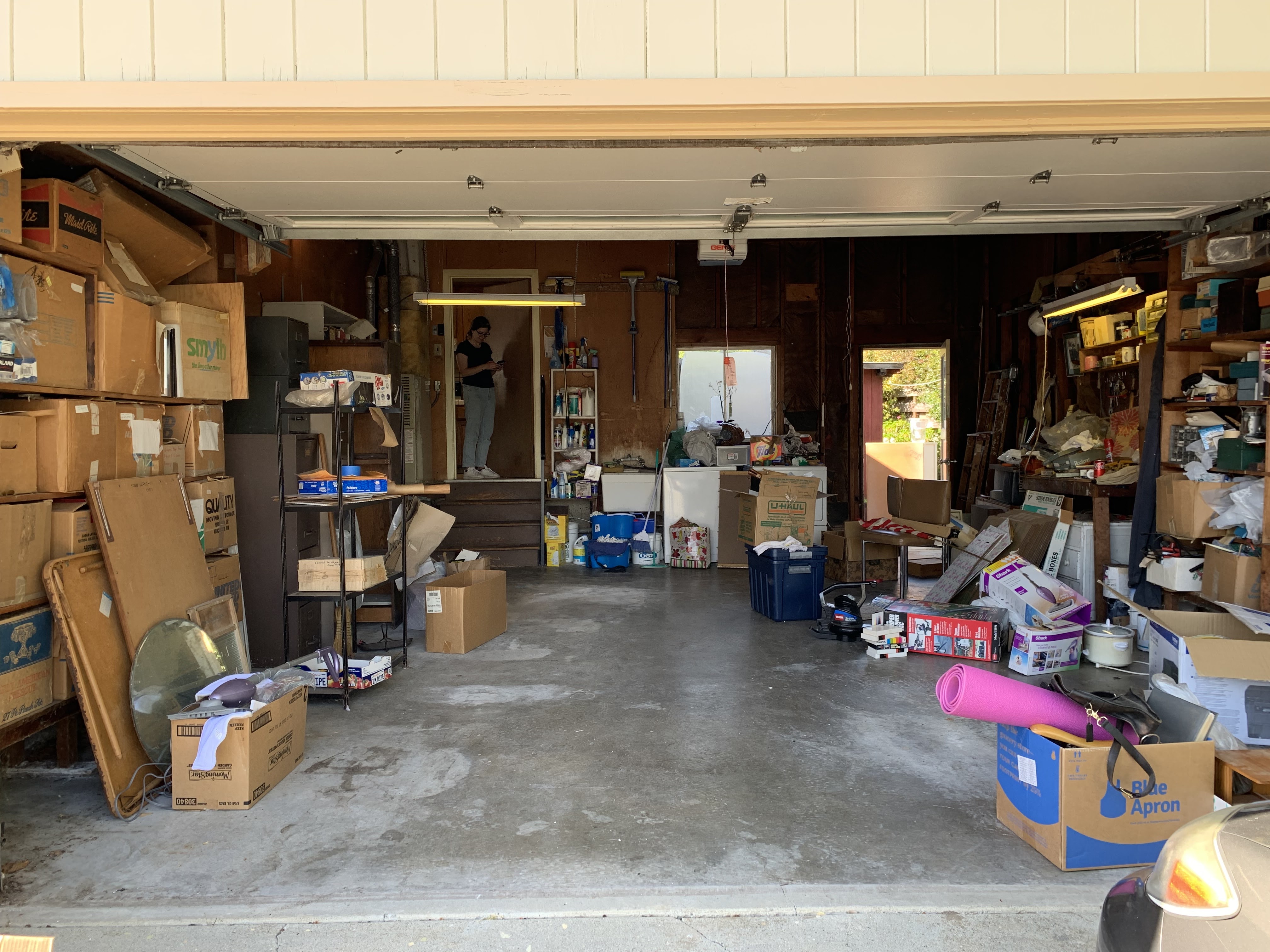
The stuff that we haven’t yet dealt with weights down the garage, makes it hard to get into the model railroad layout to do work. Every time I trip over it, I’m reminded that I haven’t dealt with the items, and the items within are slowly decaying without being used or enjoyed. I’ve got to go through the boxes at some point. Leaving them piled in the garage just pushes off the problem to the next generation, and just keeps us from doing other fun stuff with the space.
Model Trains Holding My Father’s Stories

Southern Railways locomotives at Waterloo Station during one of my dad's trips into 1947 London.

My father's photo of Flying Scotsman when it visited San Francisco
One of the boxes contained a bunch of model trains my dad had collected over the years. There was his Varney F-7 locomotive that he’d built and painted as a teenager, along with a few HO cars he’d also built from kits. He’d bought some British and European prototype trains when he visited Europe in the early 1960’s. He had other locomotives he’d bought at various times, such as a Pennsylvania GG-1 electric locomotive that he’d bought after a family trip to the East Coast. He kept some of these on display, and kept others in boxes in the garage, not wanting to lose the memories attached to them. When I’d offered to find homes for some of the stored model trains several years ago, he relinquished some, but held others; these model trains had memories of his life, and he didn’t want to let them go.
I had to keep my Dad’s Varney locomotives because he built those. The same with the half-done trolley model - for now I can’t let go something he put blood and sweat into creating.
For the others: well, my dad had strong memories for many of these trains. I’d heard some of those memories - of taking similar commute trains into London as a tourist seventeen year old, the freight car he’d gotten from a shipper trying to solicit ocean freight business. Locomotives which reminded him of childhood or his first railroad job. I’m glad he had that sentimental attachment to the trains, but that wasn’t reason enough to keep them. There’s other cases where I never heard the story. Why did he want that particular SNCF locomotive? Why did he keep that Life-Like 4-6-0 in a box for 50 years? Did it have meaning? Or perhaps there wasn’t a story. Maybe it was an impulse buy of something on a sale shelf. Did he just not know what to do when he no longer wanted it?
But Some of My Items Also Hold Stories. Do I Need to Hold Them?
And at the same time I was thinking about my father’s sentimentality, I was dealing with my own. I had my own piles of stuff with memories, and some of those piles got in the way and kept me from some of the fun I wanted to have. Pruning my father’s sentimental items encouraged me to do the same.
I cleaned out and rearranged the closet where I keep some of my model railroad gear, and picked out items that wouldn’t fit back in the closet. I cleaned off places around the layout where I’d stored anachronistic freight cars - usually freight cars from my childhood that I’d pressed back into service when I started building the Vasona Branch, but no longer needed. I picked through storage to find some old locomotives from teenage years that brought back memories of getting started in model railroading. I went through boxes of half-done projects, or badly built kits, or experiments with new materials, often highlighting memories of how I improved my modeling skills over the years.

My grad school layout with teenaged boxcar.

Getting Thomas the Tank Engine ready to be seen by nephew.
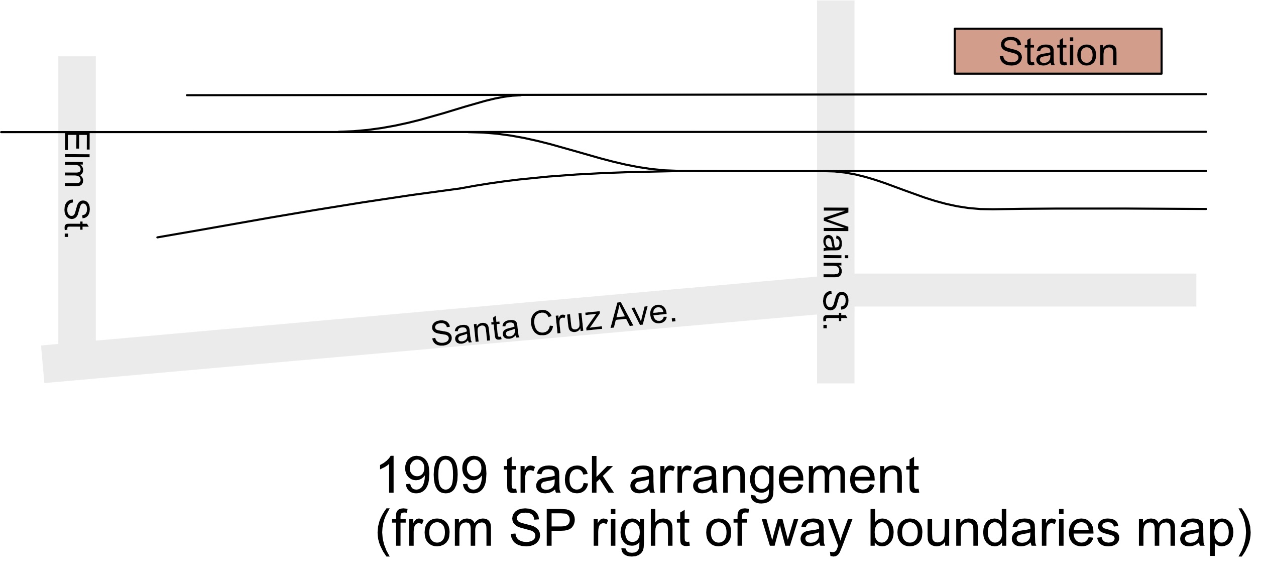
And as part of preparing to sell my dad’s trains, I decided it was time to do the same pruning on these items. Some to keep, some to throw away, some to find a new home for. I had a station I’d scratchbuilt when I got back into model railroading. It wasn’t appropriate for my current layout, and had an unrealistic roof line. I knew I could do better now. I liked the attached memory of learning to scratchbuild, but didn’t need the model. I had plastic freight cars from teenage years that brought back memories of the excitement of getting started in the hobby, but beyond that weren’t interesting. I had Thomas the Tank Engine locomotive I’d bought to interest my nephew in trains. He’s now 13, but never got the bug.
I also had model trains I’d bought as part of my own travels. One was a French freight locomotive I’d gotten at model shop in some small town in southwest France. We were staying with friends in a house in a tiny village in the middle of nowhere, surrounded by wheat fields. We left the friends by the pool and took the car one afternoon and drove several towns over to a small town which had a model train hobby shop. The owner didn’t speak English, but my wife could translate a bit. I asked about trains that would run in the local area, and he pointed out a freight locomotive and covered hoppers, and also sent me home with some French model magazines. I got a tiny Hornby OO “Smokey Joe” switching locomotive from my sister when she first visited England. I had a Chinese National Railways diesel engine and passenger cars I’d gotten on a trip to Hong Kong. I’d walked by some store in the Central district and realized they had train models (though their main business was bus and tram models.) I’d never seen Chinese prototype locomotives (surprisingly from Bachman), and the locomotive ran wonderfully. (The owner of a hobby shop in Singapore scowled when I asked about Chinese-prototype models. "Why would you want that? The stuff from China's all cheap. You should buy these Marklin engines!") I had model kits I'd picked up in the UK when on a top-secret work trip.
I’d run some of those exotic trains when I was first building the Vasona Branch. In fact, the earliest shots of the Vasona Branch - photos taken at the end of a four-day binge of building - show the Chinese locomotive testing the trackage. I didn’t have many steam locomotives in those days, and big diesels were better for checking for crooked track and braving dirty track. Some of the teenaged freight cars operated on the Vasona Branch in the early days when I didn’t have enough rolling stock to make the layout fun to operate.

I lied. The Chinese locomotive wasn't on the tracks during the first weekend of construction.
They all had memories, good memories, my memories. But they all spent most of their time in boxes in the garage, occasionally pulled out to be looked at, and quickly put back. It wasn’t much of a life for a toy meant to be enjoyed, seen, and played with.
And So The Pruning Began
The first boxes went off to some local clubs. Dad’s books went to model railroad club at the Santa Clara depot; they could eBay the salable items to help support the club, and had a big table of free stuff for members to pick through and take home. Some of the odd books my father had relating to railroad rates went to that table. Much of my teenage HO cars and locomotives went to the Silicon Valley Lines, specifically for their younger members. They were having an operating session on a Saturday, and some of their new teenage members pounced upon the box like wolves tearing apart a carcass. One kid liked the look of the battered Athearn SDP-40 locomotive I’d bought at a swap meet table at the first serious model railroad event I’d ever attended. “Looks like the clips holding the body onto the frame are broken.” “Yep, that’s because I had too much fun with it when I was a teenager. Think you could fabricate new tabs out of styrene?” He thought about it for a while and kept it.
Full disclosure: I remember multiple times in my childhood where folks were giving away unwanted toys and trains like that, and and I was so excited to just have access to all these cool things - the neighbor dumping his hot wheels when he moved away, box of modeling supplies from someone's father. Watching the kids dive into the box and want the stuff was really fun!

The British trains were a challenge. My dad had strong memories of English trains as connections to his father’s country of origin and as memories of my father’s own trip to visit England in 1947. He told plenty of stories about catching the train at a stop near his cousin’s house and wandering into bomb-scarred London all by himself. He bought trains to remind himself of that important place and his first bits of freedom in a foreign country. There was a lot of sentimentality connected with those trains, but they were also the oldest and the least interesting to contemporary modelers. Instead, they went to someone on reddit.com who was asking about how to get started with British prototypes - fingers crossed those trains will get out of the box and actually be used.
The bulk of the European models got sold at the local model railroad group’s quarterly auction - in about 10 minutes, all the items started on a path to a new home - this Marklin locomotive to an enthusiast, that locomotive to someone who sells at swap meets, a couple freight cars went to who-knows-where. My French freight locomotive went to some younger modeler who seemed to revel in its oddity; I think it’s going to a very good home.
My Chinese locomotive - well, that went off to the swap meet guy at the auction because apparently it wasn’t interesting enough for the assembled crowd. I’m a little afraid I may see it again when looking on the tables at the next swap meet. My sister had a similar bit of haunting. She’d been taking a bunch of dishes and glasses to a local thrift store, and they were so grateful for everything, even the worn stuff and the unfashionably 1970’s glasses. Late in the cleanup, my sister found the lid to a dish she knew she’d given to the thrift store the previous week, and she wanted to make sure it got matched up again. So she marched into the thrift store to pair it up… and realized their whole housewares section was filled with our parents’ dishware. Our childhood was stretched across several tables, all priced at $2 each. She didn’t go back.
So it’s all gone now, and I’m a couple boxes closer to reclaiming the garage. My father and I had bought model trains because we thought they were interesting, because we liked constructing a model railroad, or because the trains were paired with some special event like travel or a particular time in our lives. We saved these artifacts because they highlighted an era in our lives, or a milestone in building our skills, or because they were just attractive to us.
My father saved those items - sometimes on display, sometimes just kept in the garage to know they were near. I’ve saved items so I can use them actively on the model railroad, or stored away so I can run across them again. In a very few cases, I’ve saved particularly significant items.
And I’ve let a bunch of them go. For some, the memories aren’t quite worth the space they occupy. For others, a photo is enough. For yet others, I just needed to write down the stories so I could get them out of the garage and instead let them linger right here in these words.