Showing posts with label rebuilding. Show all posts

Wednesday, February 18, 2026

Keeping Up Appearances, Panel-wise

How much effort does a panel of meters and switches deserve?

When we build a model railroad for operations, we’re not just building it for our own amusement, but also as an object to be shown and operated by others. If we’re going to invite folks over to spend several hours reproducing prototype roles, we’d like to make the layout welcoming and easy to operate. Some of us with nice inside spaces (not me) might make sure there’s a comfortable area for crew to hang out in with some comfy sofas and model railroad magazines scattered about. Others (like me) might focus on usability: are the controls for switches in obvious locations, and are the locations marked neatly and in a matching style on the fascia.

There’s also the less-obvious improvements. We might declutter the layout and hide storage with curtains below the layout, or make sure the fascia is neatly painted. All of this can make a big difference in our first impressions of a layout. I visited a home layout last year in Minnesota that was beautiful - well lit, clean, in a carpeted basement. Future kits were stashed away neatly on shelves as if in a hobby shop, layout markings followed good graphic design traditions, and general cleanliness would make crawling under the layout for repairs would be a pleasant experience. I described it later as “exactly as childhood me thought all those beautiful layouts in the magazines looked.” After touring a lot of layouts, I can safely say not all of them are that clean or welcoming.

Cleanliness also affects how others might operate the layout. One of the local modelers thought that folks might be rougher on his freight cars because he had a layout that lacked scenery and a pleasant space. “Folks will be extra-careful with Jack Burgess’s cars because of the beautiful fascia and carpeting, but then they’ll be less careful with my boxcars when they can see the 2x4s and the pink insulation.” I’m not sure that’s true, but I could imagine the level of care the layout owner applies to the space might affect the level of caution that operators apply.

Perils of the C-Clamped Panel

When I was cleaning the layout up for an operating session at the last PCR Layout Design and Operations meet, I got thinking about this. A few years back, I realized I needed a place for some layout controls and monitoring. The first was to find a place for the fast clock controller with its switches: I made a Plexiglas panel, cut a hole in the masonite fascia, and dropped the panel in. A couple years later, I realized it was helpful to know how much power was being drawn from the repurposed AC adapters I was using for layout lighting and switch machine power. That added a second panel for a bunch of digital meters to monitor power use. After a couple of problems with DCC power, I got some track meters to check voltage and amperage. The location on the fascia wasn’t big enough for the new meters, so I cut a scrap of masonite to hold the meters, and c-clamped the assembly in a convenient spot - good enough for the debugging I wanted to do.

When I started cleaning up the layout for the op session, I realized that the temporary meter panel stuck out. It was easy to bump, and looked slapdash. There also wasn’t room where the existing panels were located for a more permanent and professional site. Moving the existing electronics wasn’t easy. I’d attached every panel with machine screws into the masonite in random locations - moving panels around required cutting new openings in the masonite, drilling new holes, and covering any openings from the previous locations. Changing the existing panel locations wasn’t easy.

Now, the way I’d attached the different electrical panels isn’t a big deal; most visitors aren’t looking at the panels. However, the ad-hoc way I’d done it did look awkward to my eye, and detraced from the overall look of the layout. To make it look better - and to make me more proud of my work - it deserved a rethink. I wanted something that would be more amenable to change if I wanted to change what meters, lights, and switches I had, or change their locations. I wanted the different panels to be more uniform and similar so that the set of panels looked intentional and related. Because I sometimes needed to pull out the panels to access all the electrical terminal strips just behind, I needed an approach where panels could easily be removed and replaced.

A Sound Solution

One bit of inspiration came from electronic music. One of the big trends for folks interested in sound synthesis is a system called “Eurorack” where similarly sized small electronics modules can be placed into a case and connected as needed with patch cords. The idea of connecting individual oscillators, modulators, noise sources, filters, and effect processors dates from the dawn of computer music; Eurorack’s standards define how devices from different manufacturers connect electrically and mechanically.

Typical Euroarck setup. From Wikipedia article on Eurorack. Credit: Matthew G Daniel, wikipedia.org, Creative Commons "Attribution-ShareAlike license.

Mechanically, Eurorack relies on some mounting channels from professional electrical equipment. Individual module panels are fixed height (about 5.25 inches, or 3U in electrical rack units) with widths that are a multiple of 0.2 inches. Panels always mount with M3 screws into screw holes or sliding nuts in the mounting channels. (There’s also an electrical standard for supplying individual modules, and for the audio signals at patch points; those were irrelevant to me. The idea of a common 12 volt supply and common ribbon cable to connect power might be useful for model railroad accessories, though.) Multiple electrical manufacturers sell the mounting channels which the Eurorack folks repurpose and resell.

Eurorack mounting rail / channel

Eurorack seemed like a decent starting point for me. It allowed for neat panels that could be adjusted or rearranged as needed. Matching the Eurorack size constraints avoided needing to rethink appropriate sizes for individual panels, and gave me measurements for locations of mounting screw holes and tolerances for widths. This wasn’t the cheapest way I could get panels done - screws into masonite would have been fine - but this solution would look good, allow the panels to change over time, and showed visitors and operators that I cared about appearances.

The channels use aluminum strip and screws to set the precise spacing; I put this together and double-checked the height between the channels. Once this was done, I mounted the channels to wood blocks glued to the Masonite fascia.

Finally, I fabricated the different panels that mounted in the new panel frame. I’d previously used thin Plexiglas for panels. These panels were rigid and held switches meters firmly, and could easily be painted and marked. However, the plastic was hard to drill and mill because of its brittleness. I instead decided to use 1/16” aluminum on these panels. The aluminum worked well because it’s rigid and easy to decorate, Some local folks reminded me that some of the sign making franchises such as FastSigns can print designs on aluminum, but I decided to do everything from scratch. I did markings by printing designs on transparency material and then mounting these with Spray-mount to the aluminum.

I did hit some challenges moving to aluminum.

First, the tolerances expected for the Eurorack channels are tight, so I had to be precise when cutting and finishing panels to size and drilling holes in exactly the right places. Panels that were cut a bit too large wouldn’t fit between other mounted panels and needed to be filed down. Eurorack channels can use captive sliding nuts or continuous rods with even screw spacing - the continuous threaded strips I got seemed better because they couldn’t slide behind another panel. However, the threaded strips turned out to make tolerances even tighter because of the requirement that the holes in the panel exactly match the spacing of holes in the threaded strips. Some commercial Eurorack modules use rounded slots instead of screw holes to allow some play when attaching in such cases. The precision required meant I needed to be very careful making the panels and drilling holes for mounting screws. I’d started out assuming I could use a center punch and a drill, but realized that it was too easy for a hole to wander a bit too much. Instead, I had to drill the mounting holes with a milling machine, a center drill to start the hole, and a final drill to size. I still ended up having to file holes larger if the hole positions weren’t quite right.

A second problem was with the lettering approach. Using transparent plastic allowed me to set up lettering exactly as I needed. However, I couldn’t drill or cut the panels with the transparency material on, or it would get pulled off, get metal fragments stuck between plastic and aluminum, or get damaged. I needed to transfer holes for panel switches precisely to do the drilling, then needed to glue the transparency material down in the same spot for the lettering to correctly line up with switches.

My final problem was cutting the large openings for meters. Cutting in thick aluminum isn’t particularly easy. I initially tried milling the openings, but had a hard time holding the aluminum sheet securely on my Sherline mill. I tried a jeweler’s saw next; it worked fine for openings close to the edge of the panel, but couldn’t cut openings in the middle of a 6” wide panel. I finally fell back to using a nibbler tool which was slow and painful but eventually got the job done. I’m proud that I didn’t give myself blisters this time - the nibbler tool is particularly successful at that.

The panel for control and monitoring is done now; it’s got controls for the fast clock, accessory voltage and current, DCC fault lights, and DCC meters. I still need to add meters for the third booster on the layout - for now, I had a blanking plate over the space where this may be placed.

Making the layout look good is important - both for my pride of craftsmanship, for ease of getting around the layout, and for its effect on the folks visiting the layout. Functionally, I now see all the meters which help me spot and troubleshoot problems on the layout. Redoing these panels wasn’t strictly needed for the layout, but it looks much better, can handle future change, and represented a fun project for me.

Saturday, September 12, 2020

Rebuilding Glenwood

A string of maintenance-of-way gondolas heads uphill.

Like I mentioned last time, long-suffering Glenwood got some serious rework recently. I had some good reasons to finally return to Glenwood. The ProRail invitational was going to be in San Jose in April (before COVID-19), and the visitors from around the US deserved to see the layout at its best. I needed a distraction from work, and wanted some projects that could fill a weekend.

I also had several years of pent-up frustration waiting to be unleashed. Glenwood’s also an old part of my layout; I laid the track on the upper level about two years into the layout, and roughed in some scenery. The model doesn’t accurately capture the real location. It’s not up to my later standards for prototype scenes. It's not eye-catching enough to be a focal point for the layout. Glenwood’s also in a darker corner of the layout, and in a location that’s not central to model railroad operations, so it’s never gotten a lot of scrutiny. Glenwood deserved better.

But being generically dissatisfied is one thing; I need a list of things to fix. Let’s run through the problems at Glenwood.

Glenwood before the rework.

Problems with Glenwood:

  • The road’s unrealistic, just badly-levelled Sculptamold on foam scenery, with sheer drops and no shoulders.
  • The building just above the tracks isn’t prototypical; although there was a small house there, the building on stilts doesn’t match the location, nor does it look realistic for the 1920’s. It also draws attention away from the prototype portions of the scene, hiding that great curve into the cut and tunnel.
  • I'd built a station building, but it’s a coarse plastic model. There’s none of the maintenance of way buildings or outbuildings seen on the maps.
  • The grassy hillside doesn’t quite match reality; prototype photos show more trees. The grassy hillside doesn't hide the unprototypical terrain, and misses the chance for trees as a view block to frame the scene.

So my plans? Tear out the hillside, improve the tunnel entrance, make the scene more realistic overall, and detail the station area.

Redoing Scenery

Step one was ripping out a bunch of bad scenery - taking out the hillside, the cut, and the house-on-stilts.

Before any of that, I took a pass at a bunch of other unfinished business. The turnout in front of the tunnel was a frequent derailment site. I ripped out the track, leveled it out with spackle, and relaid the track. The old Tortoise switch machine was a problem; it stuck out too far below the bottom of the deck, and was difficult to adjust. I swapped it out for one of the tiny MP-5 switch machines. I also took this opportunity to check on the track in the tunnel, pulling up even more track, using spackle to again ensure the roadbed was as level as possible, laid the track better, and sealed in the tunnel so that stray light didn’t ruin the illusion of a tunnel through a mountain.

With the track done, I hit the rough scenery.

The new hillside started out with the focal point: the road climbing over the hill and curving around the top of the tunnel portal. This road’s actually the Glenwood Highway, the first paved road across the Santa Cruz Mountains, and first state highway over the mountains. The Glenwood Highway, built between 1912 and 1921, split off from the current Highway 17 on the ridge between Glenwood and Laurel, dropped down into the Bean Creek canyon, then headed through Glenwood towards Scotts Valley. The concrete road, 15 to 17 feet wide, had banked curves and oiled shoulders. It was the height of modern highway design. When the Glenwood Highway was widened in 1939, the town wasn’t big enough for the highway and the railroad; the SP lost that battle, and the depot was torn down to encourage more space for cars. The current route of Highway 17 later won out, but the jazz-era Glenwood Highway still remains if you drive through Glenwood today.

Road during rework.

Road after rework.

Old photos show the key details of the Glenwood Highway: precise curves and straightaways, the odd slalom around the top of the tunnel portal, and an even descent. I followed an approach I’d used elsewhere. I’d started by roughing out scenery to match the rough slope I wanted, and tore out as much of the old road as I could. As I’ve done elsewhere, I used 1/16” styrene sheet for the roadway, scribed with expansion lines. I cut the styrene at the workbench so I made sure curves were accurate and straightaways were smooth. I glued the sheet to the scenery with Liquid Nails contact cement, and used weights and straight lumber to keep the road flat until it dried. Once the road was glued in place, I used Sculptamold and spackle to finish the fills and shoulders.

Time for detailing the scene.

SP 84 heading out of Glenwood tunnel towards Santa Cruz.

SP 31 coming out of tunnel.

This photo of train 84 coming out of the tunnel shows that the bottom of the canyon had a bunch of pine trees in the 1920's. I'd always intended to capture scenes like this: the conifers in the canyon, oak trees higher up, and the privacy screen of trees between the highway and the railroad tracks. Rearranging the hillside and roadway helped this a bit. Filling in undergrowth and deciduous trees is easy; I've been using either Supertrees or Woodland Scenics Fine-Leaf Foilage. The redwoods and other conifers were more of a problem. I'd covered the hillside around Wrights with Woodland Scenics conifers, but I'd found these slow and tedious to build. I'd started trying to do the same at Glenwood, but eventually figured out that gluing tufts of sponge to the plastic armatures was not how I wanted to spend my hobby hours. Luckily, I'd gone to a model railroad train show right before COVID-19 struck. Grand Central Gems out of San Diego was there with their pre-made trees; I bought a few bags of tall pines, and loved how quickly I managed to get the scene finished. I bought a couple more bags later, quickly filling the hillside. I've always been cheap and unwilling to buy pre-made trees, but spending less than a locomotive to get this scene finished was worth it. With enough trees, it was also easy to give the look of separate areas of fields separated by tree lines. Static grass and a barbed wire fence made of wood posts and fishing line completed the scene.

Turntable:

In the earliest track plans for the Vasona Branch, I’d sketched in a location for the pit for the former South Pacific Coast turntable. Glenwood had been a key spot for narrow gauge lumber traffic; many short trains would carry lumber up to Glenwood; from here, a single engine could pull a longer train through the summit tunnel and down to the Santa Clara Valley. One of Bruce MacGregor’s South Pacific Coast books mentioned the filled-in turntable, so I added it to the track plan as an interesting bit of history. I’d cut a half-moon hole in the homesite for the turntable at a convenient location when I first laid track.

In the last episode, I mentioned finding the valuation maps and spotting the actual location. There were actually two turntables. The one at north end of town that apparently was filled in and tracked over during standard gauge times. The other turntable was at the far end of the siding, hanging over creek edge. Neither matched my guess when I'd first sketched the track plan.

I’d already cut the notch in the layout for the turntable in… oh, 2005, and wasn’t up to moving it. Stories claim the turntable was mostly filled in, but I took the existing hole, added stained balsa wood around to support it, added some debris on the bottom, and called it a day. It'll be a good location to throw whatever clutter I happen to have kicking around.

Glenwood Station:

I scratch built the Glenwood depot using some existing plans, and inference from photos. Gary Cavaglia published plans for the Glenwood depot in the March/April 2003 Narrow Gauge and Short Line Gazette. His drawing laid out the original narrow gauge depot building from the 1870's. That building contained a waiting room and tiny baggage area, and was completely sided in shiplap siding. All the photos from the times I model show a different structure. Apparently, the station was extended some time before standard gauging. The 1920's station extended the office portion of the station, built on a long addition for baggage and freight, and added a large raised freight platform matching SP's standard station designs. The station, however, kept many of the details seen in other SPC depots in Alviso, Agnews, Alma, and Wrights: similar doors, roof supports, and roof peak decorations.

Cavaglia’s drawings of the depot gave me the rough shape: walls were 12 feet tall; the gable peaked at 17 feet, and end walls were 14 feet wide. The drawings also laid out the rough sides of the passenger section. During the reconstruction, a door moved; I assumed the windows stayed in the same location. Using these measurements and various expectations (doors 30” wide, windows three feet off the ground) I could infer other measurements. The waiting room originally had two windows with a door between; later photos show a solid wall and a door to the right. Apparently, the reconstruction kept windows in the same locations but blocked up the original door location.

The later extension to the freight side of the depot was board-and-batten which made guessing at lengths easier - the battens appeared to be spaced 12” apart, so I could make guesses about the overall length of the extension. I sized the freight dock to the space available on the layout, rather than the size of the prototype’s.

SketchUp model of Glenwood Station

I sketched the whole model in SketchUp because I could do so quickly - I already had 3d models for the SP-style windows, so putting together the rough shape was fast. Once I had a rough model, I could compare it to photos and confirm that it looked about right. I could have done the same with pencil sketches or with a cardboard model.

I built the model using sheet styrene, window and door castings from my hobby stash, and vacuum-formed shingle material from Plastruct. I was lucky that all the supplies were already in my hobby stash, for I started the model just as the Covid-19 shelter-in-place started here in Silicon Valley. Like many of the SP stations I built, I used the Grandt Line 5031 windows (12 pane double-hung windows) to match the main windows, and the narrower Grandt Line 5029 windows for the sides of the operator’s bay. (I use those windows a lot, so my box-of-windows-for-projects usually has some on-hand.) I scratchbuilt the freight doors from styrene sheet. It doesn’t take a lot of styrene to be able to knock off one of these models; I usually keep a couple sheets of board-and-batten material, a couple sheets of shiplap, and then strip styrene in 1x4, 6x6, 2x6, and 2x8 dimensions, and that’s all that’s needed for most buildings. I also keep large sheets of 1/16” sheet styrene from TAP Plastics because it’s cheap and useful for bases or backing support. I also had some very beefy .156 x .250 sticks of styrene; these turned out to be really handy for building up a base for the loading dock. I could have done the same with Plexiglas, but that would have required shopping, and also required using power tools in the garage. Building from styrene let me build quickly with just a #11 X-acto knife, a square, and a straightedge.

Overall, scratch building a model like this is quick - probably a week of evenings including design and painting. The worst part is cutting out the window openings. If you haven’t tried scratch building, find some simple building, get $25 in plastic from your favorite hobby store, and start cutting!

Maintenance of Way Buildings

Who was around in Glenwood? Even with the large station, Glenwood never attracted the business one would expect; it didn’t become a wine center, didn’t have a major lumber industry, never attracted farmers. The August 1916 Southern Pacific payroll on ancestry.com showed Campbell station had an agent, warehouseman, and clerk, and apparently had a part time “fruit checker”. Wrights had an agent and warehouseman in their little hamlet. Meanwhile, Glenwood’s large station only had Alfred Feldt, operator, making $80 a month. Feldt eventually moved to San Lucas; in 1920, Edom N. Davis had the agent role. The abandonment proceedings in 1939 declared that only 196 people lived in the Glenwood area.

The section gang was a big chunk of that population during the teens and twenties. 1916 payroll records show six laborers and a foreman in Glenwood, reminding us that the section housing and work sheds deserve to be prominent. The August 1916 records show similar section crews at Campbell, Los Gatos, Wright, and Santa Cruz. The 1916 crew included V. Simoni as foreman, P. Simoni as watchman (perhaps for the tunnel), and G. Simi, M. Mariani, J. Jilla, A. Scarponei, U. Balleroni, and G. Berlacgua on the crew. The 1920 census showed a similar crowd: Benjamin Capp, Vigellio Elli, Toni Gianti, G. Luciano, Joseph Menta, Sam Chientilli, and Angelo Fideli. The railroad apparently was a good gig for the new immigrants. A separate continent of Mexican workers listed their occupation as wood choppers in the same census pages. Valuation maps don't show housing for the workers, but a few 1920's photos show what appear to be bunk cars on the siding next to the tunnel. Twenty years later, a Vernon Sappers photo of the Felton depot in 1935 shows maintenance of way bunk cars on the siding behind the Felton station, suggesting the maintenance of way workers moved closer to the bright lights of civilization.

I'd hoped on hinting at the folks who worked in Glenwood. I've got some bunk car models (care of Jason Hill of Owl Mountain Models fame), but I hoped I could include the section house where the foreman lived. Unfortunately, I'd started figuring out a location too late - I already had the station and an Atlas water tank in their rough locations. Unfortunately, I couldn't figure out an arrangement that didn't appear too crowded. Instead, I added a tool house built from a A&LW Lines laser-cut kit, and an outhouse next to a privacy fence.

Scenery improved? Check. Unrealistic buildings removed? Check. Prototype station in place? Check. Tons of trees? Check. Glenwood was always a place I modeled because I wanted to capture the real look - the curve into the tunnel, the redwoods, and the interaction of the new highway and the old railroad. It’s now got that look I intended.

Wednesday, August 19, 2020

Bring in the Photographers!

Full disclosure: all photos here are mine documenting the weekend, not the shots the pro guys made.

Well, that was an interesting weekend. As part of preparations for the NMRA 2021 National Convention, Rails by the Bay, I got a chance to get my layout photographed for articles about the convention. Model railroading’s a lone wolf hobby for me, so I’ve never had anyone else doing serious photos of the layout. I instead got to sit and see how others thought of my layout, and how they worked to get great photos. I also changed a bit how I think about the layout as a result.

So let’s talk about aiming for good photos in terms of planning, preparation, and the photos.

If model railroading taught me anything, it taught me project management. Building a model railroad always involves a long effort to build something significant: deciding what to build, sequencing all the work, rolling with the voluntary and involuntary changes, and ending up with a completed model railroad. I found out about the photo sessions at the beginning of the year, and realized I had some time to finish a couple scenes that had been lingering. I used my usual tricks for deciding what to figure out what to do: fix what annoyed me the most, and fix what I was in the mood for.

Two projects won. First, long suffering Glenwood’s scenery finally got redone. I’ve written a bit about that previously, but to recap: it has the potential for an eye catching scene, the prototypical curve makes it easy to stage reproductions of historical photos, and who doesn’t like model trains in mountain scenery? I’d first ripped out the old scenery and fixed some notoriously unreliable trackage near and in the summit tunnel. I redid the hills and Glenwood Highway to better match the terrain. I then covered the area in trees. Normally, I try to build trees from Woodland Scenics kits, but this time I bought from Grand Central Gems at a recent train show, and had a redwood forest ready in days. I ballasted track, detailed the former turntable pit, and built a quick reproduction of the Glenwood station from styrene. (I’ll talk more about the station another time.). Glenwood needed a water tank, so I quickly grabbed one of the venerable Atlas kits and put it into service.

By the time the scene was done, COVID-19 had hit and the original deadline for the work - the Prorail operating event had been cancelled. We rescheduled the photoshoot for August, which gave me motivation for another project. This time, I decided to go after downtown Campbell. The Campbell scene’s always been a focal point for the layout, but the scenery and structures have been half-done for years. I’d built the station model years ago and scenicked the station side of the tracks. However, the opposite side of the tracks was still temporary buildings and little scenery. That included downtown Campbell, Sunsweet, the Hyde Cannery, and Ainsley cannery. This area provided some great scenes - space to photograph long trains, switching action, and lots of canneries. I started on a big push a couple months back to redo everything. For downtown Campbell, I redid the road and building bases, and started trying to pull all together.

I’d already done four of the five buildings for the downtown Campbell Ave., but had held off on the most impressive of the group - the Growers National Bank building that had been downgraded to the local movie theater by the 1930’s. (The building still exists in 2020, though I think they're still fighting about whether to allow it to become a night club.) I’d made a couple attempts at starting the bank, finding a suitably regal plastic model, but the space on the layout was tiny - only about twenty feet wide - and the model wouldn’t fit. Unable to do things perfectly, I just gave up and decided I’d do the model another day.

That day finally came as I cleaned up Campbell Ave. I tossed out my ideas of a "perfect" model and decided to just start building and see what turned up. Like the Dutch signal box, I finally got annoyed enough to just start building. Like that model, I used styrene sheet primarily. Again, large dimension styrene rod worked really well - the 2 foot inset for the doorway was simply 0.250 styrene bar, simplifying the construction. A leftover door and window served for entry. I used brick sheet for the walls; the detail along the roofline were strips of board-and-batten siding standing in for carved stone. I crafted the theater sign from styrene sheet. I would have liked to 3d print it to get the lettering perfect, but my older SketchUp software doesn’t seem to want to render 3d characters.

<

Campbell Theater

Bank of Camera Close-up

With Campbell Ave. in, and the road glued down, my next project was fixing the Ainsley Cannery. The Ainsley site’s had a posterboard mockup ever since the layout was built; I still remember Byron Henderson complimenting me during an early operating session because the freight door spacing matched my 40 foot freight cars. Back in 2006, I had a great solution for the cannery - I’d found a YesterYear Models “fruit packing house” - actually a former Sunkist packing house from Riverside, California. The box has been gathering dust ever since as I waited for just the right inspiration to use it for the cannery. This was finally the time to pull the kit out of storage. The overall shape of the buildings are similar - both were a row of wooden barn-like buildings. Like Sunkist, the Ainsley cannery had an office in the end closes to Campbell Ave, and a loading dock dominating the front of the building. As a result, the rough arrangements of windows and doors would work fine as-is. One big difference was that Sunkist’s building had two joined wooden sheds, while the Ainsley cannery had two corrugated iron sheds and two wooden sheds in a line; historic accuracy went out the window in order to get a "good enough" model done as I ignored the corrugated iron sheds. I ended up cutting the Sunkist building in half, and using both ends side-to-side, and ignoring the different materials in the various sheds.

The Drew Cannery, formerly Ainsley

Preparation

All that major work took me up to last week. However, I still hadn’t done much of the preparation work, so I kicked into a big cleanup mode. Our photographers recommended doing a serious cleaning so extraneous dust or debris visible on photos. I also got rid of all the little problems I'd ignored over the years. Some was operating session damage - having folks handle models is always going to trigger a bit of damage. I fixed broken signs and bumped trees, repaired damaged cars, fixed scratched paint or bent grab irons, and filled in ballast holes triggered by past cleanups. I dusted off a set of “good cars”, and stashed away cars that were the wrong era or had visible damage. I fixed long-lingering projects -holes in scenery I’d never addressed, half done patches, and rough surfaces. Some were really quick - I’d never patched scenery when I’d rearranged the Wrights tunnel. Some were larger, such as finishing half-done spackling in the Meridian Road scene.

Most of the preparation work was the same I’d do for an operating session. For operating sessions, I’d also be worrying about reliability, cleaning car and locomotive wheels, testing that engines were working fine, testing couplers and trucks. None of that sort of work mattered much here - the trains would be stationary in the pictures. I was pretty relieved not to be doing a serious cleaning. Serious cleaning's always a huge time sink, and I always want to over-prepare - I’m always worried before operating sessions whether a balky engine or dirty track will make for an unpleasant operating experience.

Another great advantage of photos is that locomotives don't need to run well. The real Vasona Branch likely had small 0-6-0s switching the canneries. On my model, larger 2-8-0 locomotives instead get the job. I really like the little 0-6-0s, but can never use them for operations. They tend to be balky runners and stall way too easily. When operators are focusing on how to solve a switching puzzle, the last thing they want to do is deal with a stalling or broken locomotive; it interrupts the illusion of working on the railroad, and usually ends up with waiting for the layout owner to clean track, fix the engine, or provide another locomotive. With photos, however, a balky or stationary locomotive isn't a bad thing, for the trains don't need to move in a good photograph. I cleaned one of the rarely-used 0-6-0s, and it got a few chances to be on center stage. To be fair, it's still good to have working locomotives if only to quickly pull cars around the layout to a new photo site, but a photo session removes a lot of the worry of mechanical problems.

While some tasks such as wheel-cleaning and locomotive tuning don’t make sense for photos, other tasks not needed before operating sessions were needed. I’m usually a bit hesitant about putting detail on the layout. It’ll often get damaged during operating sessions. I’ve hoarded some details so they’re available when I need to fill in a scene to be photographed. The layout hasn’t always been at a stage where it’s ready for detail.

But hey, if the layout’s going to get photographed for real, this is the time for all that detail. I pulled out my box of various details I’ve hoarded during my time in the hobby. Every Woodland Scenics pallet I’d ever gotten from a detail kit went on the layout. Extra parts from a Fine Scales Miniature kit that couldn’t handle more crowding. All the 3d printed boxes, bags, lugs, and can stacks I’d printed went on any available loading dock. I plopped down figures where they were appropriate. I took a pair of 3d printed flagmans shanties and phone booths and placed them wherever they’d fit. I took the large fruit bins from the YesterYear kit and made a box yard for Del Monte #3, just as can be seen in photographs.

I also put in a bunch of telegraph poles along the right-of-way. I’ve had these on the layout before; they tend to get a lot of abuse, but they’re eye-catching. This time, I spent an evening assembling and painting a set of telegraph and power poles from Rix Products and Atlas. I also painted them a bit more carefully than before. Previously, I’d just painted the telegraph poles a quick brown and added a bit of green for insulators. This time, I made the colors stronger than last time - darker posts, silvery supports, green insulators. In place on the layout, they really catch the eye. For the Meridian Road scene, I also made a point of doing a power/telephone line paralleling the road which helps to make the scene even more realistic.

And thanks to some crazy times at work, I crammed a bunch of this work into the last week, and into a mad three days. We were also in the middle of a serious heat wave here in San Jose, so the hardest part was avoiding heat stroke in the garage, but on the plus side the matte medium dried really, really fast. The roof of the Ainsley cannery got painted just as soon as the glue holding the paper tarpaper on appeared to stick. I laid ballast in a bunch of places that had never been ballasted, and managed to paint and clean the rail in time. I decorated new scenes - bushes hiding a farmhouse along Meridian Ave, a path to the bathroom around the edge of the Rio Grande gas station, and a row of posts to keep parked cars away from the Campbell depot. I was bouncing back and forth between touching up scenery, weathering cars, and touching up structures. When I was checking old photos to get the sign on the Ainsley cannery declaring it to now be the Drew Cannery, I noticed a speed limit sign, and quickly printed up several of those to control the HO scofflaws. I was still touching up ballast and fabricating a set of stairs for the Glenwood depot a half hour before the photo session.

I never completely believed those model railroad magazine articles where someone built a well-detailed layout in a year or two. I couldn't imagine they had time to decide on models, do the construction necessary, or add the details. This week's mad rush convinced me it was possible. All I needed was some definite ideas of what should be built, an urgent deadline, a bit of wiggle-room on what counted as "good enough", some well-stocked supplies, and way too much manic energy.

And the Photographers Arrive

Dan and Doug, the photographers, were spending several days just photographing layouts in the Bay Area. They've also done this before for previous conventions and other layouts, and came fully prepared. Although I've read about model photography in magazines, this was my first chance to see pros in action.

They came prepared: lights, power cords, and various secret photographer paraphenalia. The extension cords helped when the breaker blew on the garage circuit - our 1960's house wasn't designed for this kind of model railroad lighting, and we quickly found another circuit to share the load.

Dan also had lots of cool tricks so he could get into the scene with his SLR - mirrors to capture scenes the camera couldn't reach, beanbags to hold the camera steady on the layout, high tripod for the upper level photos.

And they took photos different from me, too. Some of that was expected: they visited the Vasona Branch for only a couple hours, so they were very careful to make their plan of shots, then slowly move around the layout to hit each.

Big difference number one from my attempts at model photography: they bring in lots of light. The Vasona Branch has a mix of lighting: the garage lights are cool white fluorescent strips, but I've got various cool white LEDs and warm white fluorescent fixtures lighting the lower deck. I'll usually just use the existing lighting when I take photos; if I'm really taking care, I might borrow a couple bright lights from one source or another. As a result, my photos often have weird colors if a scene has a mix of LED and fluorescent lights. Dan and Doug used two or three photo lamps. Their lights quickly overpower any layout lighting. They also didn't seem to worry about the narrow space between decks - bounce light off objects was enough to light the scene. Their biggest concern seemed to be getting the scene evenly lit, and avoiding shadows on the backdrop. In places where they couldn't get lights, they assumed they could photoshop in some sky into the black background of the garage door.

Dan and Doug use mirrors and a hand-held photo light to capture a train approaching Alma station.

Big difference number 2: The big surprises for me was just seeing what caught their attention. I haven't seen their photos yet, but they understandably looked for interactions between trains and the world. Signals were a common tool to add some action, as were road crossings. My best guess is that model photos need the extra busy-ness and action, and really need some focal point other than the train. The Vasona Branch's semaphore signals were common places for photos. (That was also true on the prototype; one real photo that inspired me is a 1920 photo of a passenger train coming into Glenwood. That photographer, like Dan, made sure to catch the train as it "split the semaphores".

I also heard a bunch of interest about the farmhouse and orchard sitting in the blob where the tracks turn from San Jose to Campbell. This scene's always been half done and cluttered - details not glued down, ground not quite sloping correctly, the orchard too small to be realistic. I'd done a big cleanup of the scene in preparation for the photos - pulled out details, removed structures, and generally made it innocuous. But interest kept drifting back towards the farmhouse and barn. I'd started thinking about details as I was doing cleanup; I'd added a hedge to protect the farmhouse from the busier road. But the interest makes me think I should more seriously plan the scene out.

Dan and Doug also focused on the large details - freight cars and car models - rather than smaller details - not surprising because of the short time. They did spot one broken crossbuck that would have detracted from the scene; we pulled it out.

And that was pretty much it; they got ten good photos, and moved onto the next layout. I got to stare at the layout for a while; it's always fun to see the layout when it's been cleaned up for an open house or an operating session, and doubly-good when all the usual clutter in the garage has been relocated. Even though I'd crammed a bunch to get the layout in shape, I was still excited enough at seeing the layout in good shape that I finished off a couple projects that hadn't been done in time, replacing a remaining broken telephone pole, putting in some gravel around the Ainsley cannery, and fixing up the famous black walnut tree that sat at the start of Campbell Ave.

What did the photos show? I've seen the first photos, and they're great - Dan uses Helicon to combine photos taken at different focal lengths to get more depth of field. Looking at the photos, I see a few things to do differently.

  • I'm vertically challenged. In a few of the photos, it's obvious I've been less than good at making sure everything's standing up straight. They're close, but as soon as several objects are in a photo: semaphores, building, water tank, telephone poles - it's obvious each has a slightly different idea what "up" is. I'll need to work on this, both ongoing, and fixing the more obvious offenders before I next take photos.
  • Prepare for the story. I'd made sure to have cars set up in sample trains, but hadn't been good about choosing cars or trains to illustrate themes I'd want in an article about the layout. For example, large industries and lots of indistinguishable red boxcars is a big part of my layout, but I neglected to have a switcher ready at Plant 51, and also didn't make sure that the cars there were the uninteresting ones. I need to sketch out the story I want to tell beforehand, and share it with the folks doing photography.

What's next? The layout's clean and in good shape, and I'm excited to do some more building. Finishing Campbell is an obvious next step: the Hyde Cannery buildings are screaming out to be build. I'd held off on building the Campbell Theater and Ainsley Cannery because I wanted to make sure I did them right. However, my quick-and-dirty building rush seemed to work with these. Maybe I should just go build Hyde and see what happens?

The orchard scene's another obvious project.

Once both of those are done, there's obvious holes to fill. One advantage of cleaning the layout was that I got rid of all the building placed on the layout "temporarily" for lack of better space - a couple of farmhouses that never found locations, a drive-in market built for fun, a bunch of cars that needed repair. Now that the layout's opened up, I'm reminded that the area between Campbell and Vasona Junction is still completely empty. The Del Monte Plant #3 property's also still occupied only by foamcore buildings. There's also a stretch of bare plaster up on the upper deck near Alma. I'll need to take a pass on any of these scenes going forward.

If the last week's any indication, I know how to get those scenes done quickly: lock down my idea of the scene, build something that's "good enough" rather than waiting for perfection, and pull a bunch of all-nighters during a heat-wave.

Friday, March 20, 2020

Rolling Back to Glenwood

Southern Pacific train #84 rolling into Glenwood around 1913.

A few weeks back, I finally started redoing scenery on a long-ignored part of the layout: Glenwood, on the upper deck. When I first built the Vasona Branch layout, I’d thrown in some temporary scenery... which has lasted for a good fifteen years now. Before I show off what I’ve been doing, though, let’s chat a bit about Glenwood.

As we read in the abandonment filing, there wasn’t a lot to do in the Santa Cruz Mountains in the 1930’s: little industry, few people, and a railroad line that tended to get buried in mudslides every winter. The Los Gatos-Santa Cruz branch wasn’t a happy place for a profit-focused railroad.

My Vasona Branch layout models the Santa Cruz Mountains on the upper deck, both for extra mileage and for my chance to model some classic California scenes. I chose to model three locations on the layout: Alma, Wrights, and Glenwood. I chose each for scenery and track arrangement reasons. Alma and Wrights were both on the uphill side of the climb to the summit, so they made sense for the slowly-rising upper deck. I chose Alma because I wanted its passing siding, and because I could find photos of the station. Wrights was an obvious place to include; the track comes up the narrow canyon, then makes a sweeping curve across Los Gatos creek to dive into the summit tunnel. The creek and bridge, toy station, tunnel, general store, and historic location made it photogenic and proper for the layout.

But what about the Pacific side of the line? I could have modeled Felton, with its lumber mill. I could have modeled Laurel, with its tiny station sandwiched between two tunnel portals, and side-hill trestles keeping the track from sliding down into a canyon. Glenwood, however, had a tight curve at one end of town that led to the Glenwood-Laurel tunnel, just perfect for the curve on the layout, which made the model in the garage match the real-life terrain. But in the 1930’s, Glenwood was near abandoned: a main line, two weed-infested sidings, and a closed station. So why include it?

Glenwood had been much more important in the narrow gauge days. Bruce MacGregor notes that Glenwood was nearly at the elevation of the summit tunnel; if the South Pacific Coast railroad could pull lumber and other freight to Glenwood, they could easily pull it through the tunnels and down to Los Gatos and San Jose with a single engine. As a result, Glenwood originally had multiple sidings for assembling larger trains before pulling them to the Santa Clara Valley. Glenwood also had a turntable for turning the locomotives hauling the lumber up from Boulder Creek and Felton, and a couple sidings for maintenance-of-way.

Beyond that, Glenwood wasn’t particularly exciting. Tunnel at the west end of town to Laurel and the summit, bridge over the creek at the south end (and eventually leading to the tunnel to Zayante and Felton), the depot, a general store, a winery that looked more like a barn, and a few houses. Some resorts were scattered in the trees, but it wasn’t the most cosmopolitain of places. It made up for its meekness with stories from the early settlers, including “Mountain Charlie” McKiernan, who famously fought a bear and got a dent in his skull.

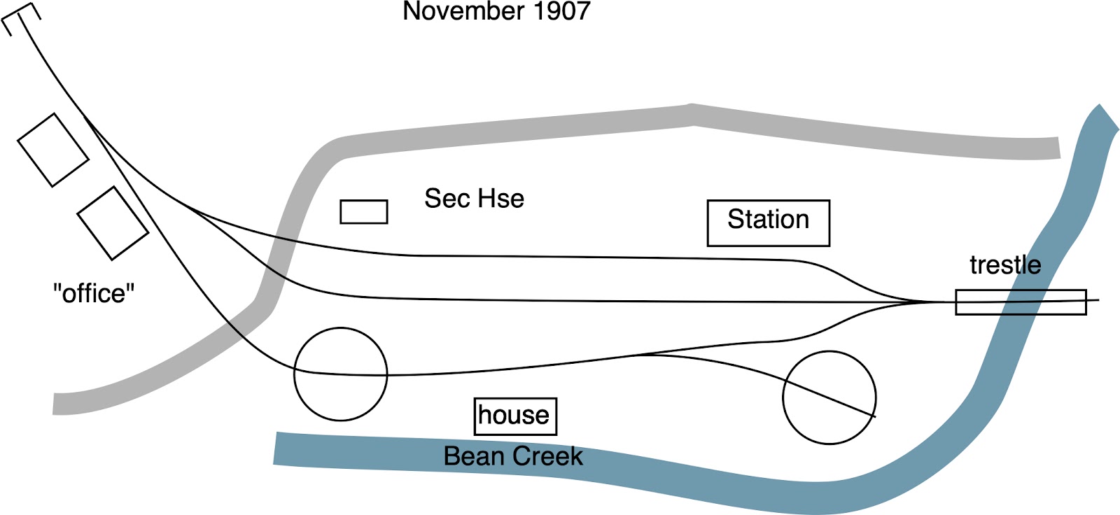
The California State Railroad Museum has the station plan drawings for multiple years, giving us a chance to see the evolution of Glenwood from the railroad’s point of view for four times: November 1907, December 1907, 1913, and 1939.

A November 1907 valuation map (probably while the line was still narrow gauged) shows three 700 foot sidings, a turntable on the east and west ends of town (the west one apparently filled in), a section house. Bean Creek, awfully close to the railroad tracks, shows up as a 10 foot gully stretching along the scene. The sidings ended just east of the depot where the tracks crossed to the west side of the creek. The current Glenwood Highway doesn’t yet exist; the downhill stretch is labelled “Vine Hill Road”. The road crossed the tracks just west of the station, and proceeded across the creek and up the hill on an alignment that’s no longer a public road. We see a section house (residence) and multiple structures along the tracks.

A month later in December 1907, the SP created another map, probably showing line changes after standard gauging and reopening the line. There’s now just two sidings and the main line, with a spur in front of the depot. Bean Creek’s now been filled in with a concrete culvert.

The 1913 map shows additional changes. This map labels the building next to the Laurel tunnel as “watchman’s house”. There’s also two spurs, probably for maintenance-of-way. There’s a couple photos from about this era showing trains passing the semaphores just before the tunnel. Those photos caught maintenance of way cars - or bunk cars - sitting on the siding. On the east end of town, longer sidings both cross the new culvert to create 1100 foot sidings for longer standard gauge tracks. The maps also show the block signals at each end of town. A private road loops over the top of the tunnel portal; this will eventually be the Glenwood Highway.

The 1939 map shows that very little changed since 1913. The track arrangement’s similar; the only differences are in the roads. On this map, there’s now a section house, tool house, and signal maintainer’s tool house. The depot was torn down to give room for the state highway. There’s also a derail on the east end of town so runaway cars won’t roll all the way to Santa Cruz.

So what do I want from all these sights? I’m not changing the track layout, so we’ll still have the curve into the Glenwood-Laurel tunnel. The Glenwood Highway looping over the top of the tunnel portal is a well-known design, so I’ll need to keep that. The depot’s small-ish, photogenic, and has an appropriate location so we’ll need to keep it. (I’ve got a placeholder model based on some plastic kit, but it’s time to make an accurate version.). I hadn’t known about the section house and tool house; there’s space for both next to the depot, so those deserve to be added.

What’s already there? The old scenery has the Glenwood highway curving over the tunnel portal, but the climb out of town is jerky and doesn’t look smoothly. There’s also a house on stilts right next to the tunnel portal. It’s unprototypical; that hillside looks like it was mostly trees and bushes. It’ll need to go. I’d also cut a space for one of the abandoned turntables. Stories suggest that the turntable was filled in, but I’m willing to leave it as a hole in the ground.

Next steps: Let’s start swinging the hammer and changing some scenery, then let’s scratch build a depot!

Sunday, May 26, 2019

Model Railroads and Technical Debt

Model railroading has taught me a lot. I can identify solvents by smell… and get nostalgic when I smell Dio-sol or Dullcoat. I learned how to repair mechanical devices, and convinced someone I might be a keeper when I fixed her CD player. Most importantly, I learned how to be kind to my future self, because I try to remember to make it easy to fix stuff on the model railroad in one year… or in ten years.

That’s a common lesson for model railroaders. Model railroads are long-term, large projects. The model railroad we build is going to last for several years, and we’re going to be expanding and repairing it along the way. The design and implementation choices we make years before will curse us years later. One badly placed switch machine is going to leave us with a sore back every time we repair it. Each time we cut corners wiring, we’re just forcing future-us to try to figure why that blue wire’s hanging loose, or remembering the wire color we used when we didn’t have black wire available. Every bit of track we can’t reach will be our bane every time a locomotive stalls or the track needs cleaning. Every model railroader has that moment of “what was this purple wire for, and where does it go?” early on in the hobby. After that we realize the benefit of using standard colors for wires, providing good access both to the track and to the mechanical and electrical parts below the layouts, the importance of labelling connectors and writing down designs - doing anything we can to avoid past-us making life difficult for future-us.

It turns out that’s a pretty useful skill in the real world, too.

I got to move some equipment I’m running into a new computer room the week before last. After I’d finished wiring it up, I asked one of the IT guys for help with something else. When he came over, he immediately commented on the state of the rack. “Wow, you’re using cable ties. And your wiring is neat - not like that other engineering rack.” He showed me the proper way to cable tie wire loops was with two ties, but he seemed pretty impressed that a software engineer was trying to keep wiring neat. The other rack, which I’d just moved my stuff from, had so many cables coming out the back that I couldn’t reach in to disconnect my machines. To be fair, the other folks in the rack were reconfiguring their stuff daily, and had a lot of connections to support; I was setting mine up for a single, long-term configuration with a much simpler configuration. Google’s original “cork board” server racks - now in the Smithsonian - highlight that you can be pretty successful even with messy wiring.

But model-railroader me was also wiring that equipment in the same way I’d want to wire the model railroad. I remembered the messy wiring on my first model railroad, and the pain I caused future-me. As a result, I made sure to steal cable ties from random benches, chose different colors for all my different cables, and neatly routed the wiring so I could get to the equipment and track down cable paths. Future-me (or future team-mate reaching in that same rack) should have an easier time, all thanks to past-me placing switch machines in inaccessible chambers between sheets of plywood, or tracking down intermittent shorts when teenage-me was splicing together wires with a couple of twists and bit of masking tape for insulation.

We worry about the short-cuts in computer programming just as we do in model railroading or in physical engineering. It’s become a popular topic in software engineering research as “technical debt” - delayed cleanup or quick-and-dirty implementations that complicate or block future changes. There’s even mini-conferences on the topic with research papers titles like “How do Software Practitioners Discount the Future?” Real engineering has technical debt too - think how commuter rail choosing to use low-level platforms (boarding at ground level) might never be able to move to high-level platforms (level surface from platform to passenger car) because of the problems transitioning from one to another. However, software tends to have more of these kinds of problems because everything’s up for grabs in software - we can build stuff any way we want, we don’t necessarily have conventions about how to do common tasks, and it’s often difficult to see those shortcuts from the outside. It’s common to tie together two bits of software with the ugliest, most fragile hack “that’s only needed temporarily”, just as I used alligator clips to temporarily tie together the power for two strips of LED lighting today. That’s less common in more traditional engineering disciplines; as far as I know, petroleum engineers never say “Joe, you sure you want to use cardboard tubes to join those two parts of the refinery while you’re testing?” (If you want a more nuanced argument about technical debt in software, read Kellan Elliot-McCrea’s argument that the term technical debt is mixing up a whole bunch of reasons why we have problems maintaining the things we build.

My current job involves writing tools to help software engineers build better programs: programs to test that the software can be built correctly, runs correctly, and has the performance we expect. Because our team has to have our infrastructure ready so that everyone else can make progress, that means we’re often building stuff as fast as we can, cutting occasional corners, and incurring technical debt so everyone else can build the things we sell. I occasionally take the same shortcuts in model railroading. Occasionally I route wires in ways that’ll make it harder to track down problems, or I’ll avoid adding a terminal strip to save on wire but minimize testing or change possibilities, or I’ll leave a switch machine near a joist where I can’t easily get to it. It’s ok in moderation, and it helps me make progress on the bigger task of building and completing the model railroad I want to build. I’ve been describing technical debt for our tools as us not trying to make future-us suffer too much, but acknowledging that some of our choices will make future-us suffer a little bit. “In ten years, we want to be laughing about the short-cuts we took and the pain it caused, not crying about a shortcut that kept us from meeting our real goals.”

That’s not a bad rule for the model railroad, too. As I was cutting in a new circuit for some LED lights for the lower deck, I wasn’t perfectly happy with how I was routing the wires, but I wanted to get everything completed and back together again tonight because keeping everything running is also a good engineering goal. And with luck, I won’t remember tonight’s short cut; if I do, I’m certain I’ll be laughing about the short cut in a few years once all the fluorescent lights are replaced by LEDs.

Saturday, August 20, 2016

A Model Twenty Years in the Making

Original Rio Grande Oil model, from 2001 or so.

It's amazing how long some projects take to build. Take, for example, this gas station. The original Barnsdall Oil company filling station, located outside of Santa Barbara, showed up in a Model Railroader magazine article back in April 1979. Teenaged-me probably saw the article just as I was getting serious about model railroading (and still reading issues at our public library.) It took me well into the 1990’s before I tried building a model of the gas station myself.

I'm really proud of that model. The cupola, dome, and roofline required some fiddly work. I'm also particularly proud of the beam ends and post detail on the roof over the gas pumps. I still see all my flaws, though. The actual building had alternating blue and white tiles - too hard for me to paint. The dome, carved out of balsa, isn’t very round and I didn’t really get the feel of the multicolor tiles covering it. I also showed the cupola as four-sided, when photos of the actual gas station show height lath-covered openings.

Worst of all, I didn’t bother to reproduce an elaborate set of detailed terra cotta panels along the roofline. The original Model Railroader article highlighted the geometric patterns on the terra cotta, and suggested lines could be carved into plaster applied on the model. I tried a different approach during the original build; one of my junk boxes still has the sample panels made of Fimo clay, hand-scratched with lines approaching the design. The Fimo result was too coarse, so I gave up on the detail and instead just cut out plain styrene to hint at the outline of the panels. I hated the lack of detail, but at least the model was done.

Why Bother With That Detail? Why did I bother to put all that detail into a little plastic model for my layout? Because even though the actual gas station is far away from San Jose, the design is eye-catching and very representative of the 1920’s in California. The gas station's style is called Spanish Colonial Revival. The style had a bunch of origins - interest in Spanish California starting in the 1880s (with publication of the novel Ramona) and hotels in Florida, but the style really exploded after the San Diego Panama-California Exposition used it for all the exhibition buildings. You can still see them in Balboa Park in San Diego. The style dominated Northern and Southern California in the 1920’s and 1930’s, for commercial and residential structures — just like mid-century modern took over thirty years later, or post-modernism changed our shopping malls and houses to brightly-colored stucco in the last 20 years.

Spanish Colonial has several branches, borrowing inspiration and details from the California Missions, classic Spanish architecture, and the architecture of Mexico and other Spanish colonies. Buildings tended to be low to the ground, with simple rectangular shapes, thick stucco walls, and hand-build details - doors with board detail, hand-forged ironwork and lamps, and tile roofs.

But many buildings went one step further - to the Churrigueresque style from Spain. Churrigueresque - definitely not a word you see much - refers to a very decorated and ornamented style often seen in Spain in the 17th century. Churriguesque buildings had facades absolutely covered carved or cast detail. Patterns could be abstract (like Moorish architecture), natural, or include human sculptures, shields, and the like. The Balboa Park exhibition buildings are particularly good examples of the style.

The Barnsdall Oil station, like most Spanish Revival buildings of the time, borrowed from many of these influences. The tile roof, rafter ends, plain stucco walls, and primitive bathroom doors all scream Mission Revival. The alternating-color tiles might be Moorish - or might be just practical. However, the two-story tower is completely twentieth century, built so the station would be visible as a Ford Model A driver accelerated up the hill from Goleta. And all that terra cotta at the roof line? Churriguesque.

This gas station isn’t the only building I know with that kind of detail. Another model I'd love to build is the Borchers Brothers building supply store, located next to the old Market Street station in San Jose. When Borchers built it in 1923, they built a brick building, but borrowed a bunch of Spanish Colonial Revival styles, then topped it off with a large window framed with similar elaborate terra cotta churrigueresque detail. I’ve got a great place for a model of Borchers Brothers, but I never knew how to pull off that window. I suspected 3d printing might help, but all my attempts ended up in the trash.

Inspiration

Rio Grande Gas Station, Goleta (Elwood) Calif.

So fast forward to a few weeks ago. We were driving back from a family trip to Disneyland when I realized we’d be passing that famous gas station, and I managed to convince Dear Wife that we ought to stop to stretch our legs. The gas station's still there along old Highway 101, just west of Goleta. It's boarded up and has obviously been unused for years, but somehow managed to survive. I got quite a thrill spotting all the details I got right - the rafter ends, carved detail in some of the posts. I also saw the elaborate terra cotta panels on the tower. There were bits missing, but the majority of the panels were still there

Detail of terra cotta panels.

The photos in that 1970's Model Railroader article were good, but they didn't really highlight the detail on those panels. Being there in person meant I could see the pattern, and also reminded me just how the tiles were the centerpiece of the whole building. Back home, I realized that my existing model - with flat styrene in place of the panels - really missed what was special about that gas station. Time for me to try again to capture the model.

The Panels The key for reproducing the panels would be getting the basics of the pattern correct. Terra cotta details for a Spanish Revival building can go a bunch of ways. Patterns could be geometric (as in Moorish Revival). Others, like the Borchers Brothers building, have floral patterns - acanthus leaves from Corinthian columns. Looking closely at Barnsdall Oil, I realized most of the patterns were swirls and spirals - volates, as the art historians would call them. Most patterns actually have two spirals going in opposite directions joined by a short segment. Many were paired together, looking like a U or shield.

I tried two approaches. First, I tried avoiding all that nasty 3d drawing, and instead tried to get a line drawing of the art from the photo. My plan was to take the detail as line art, emboss it so that the details stuck up, then 3d print the result. Photoshop and similar photo editing packages have ways to take a photo, square up the image, and adjust contrast enough to highlight the detail. However, I wasn't able to convert the photos into the shapes on the panels.

Instead, I simply started trying to reproduce the curves in the design in SketchUp, the 3d drawing program I use most. Once I spotted the volutes, the drawing process was straightforward. I just needed to build up some of the repeating shapes from multiple spirals, then plop in a few extra to fill in. To be fair, it’s actually more difficult than that - there’s several different spiral shapes and carvings.

SketchUp isn't great for compound curves, but three nights of work gave me a decent first version. I was also able to reproduce that round window, sunk well back in the wall. My original version of the model used a round Grandt Line window set just behind the wall - decent, but not faking deep adobe walls like the real gas station faked.

3d Printed Terra cotta panels, O scale

Once I had a 3d design drawn out, I 3d printed a set on the Form One printer, test-fit them to my model, and found I'd misjudged the dimensions of the tower. I stretched the design, printed again, and got some decent versions. Finally, I took a deep breath, picked up my original model, and pulled off that plain styrene sheet trim, cursing how well I'd glued it on the whole time. I even had to break out the Dremel to grind off some particularly well adhered bits. A bit of superglue attached the new, detailed panels. I repaired the stucco with the same technique I'd used originally - a mix of white glue and gesso. The combination dries really quickly, so I brushed it on then stippled it with a brush so it would have a stucco-like finish. A fresh coat of white paint (gesso) made the new stucco match the old.

I also printed a full set of panels for an O scale model, just in case I want to build another model of this gas station from scratch. Being able to scale up the part and print it for a different scale is easy to do with a 3d printer, but impossible with any of the 1970's approaches to making the gas station.

The Finished Model

Original model with new terra cotta panels.

Here's photos of the gas station with its new detail. There's still some incorrect details - the terra cotta "point" isn't quite the right shape, and the pattern isn't a precise match to the actual gas station. Still, I'm really pleased with how the extra work came out. I'm more pleased that 3d printing helped me solve a problem I couldn't fix twenty years ago.

Sunday, July 19, 2015

Research Road Trip: Road Routing Proof, and More Projects

As much as I care about modeling prototype scenes accurately, I also realize I'm using the historical research just to help me figure out what to build as part of a hobby and relaxation. The model isn't meant to be a perfect representation of history; sometimes, I'll build stuff because it's fun (ex: the Goleta gas station sitting on Meridian Road) or because a particular model might not be perfectly accurate, but it still gives the sense of the Santa Clara Valley I'm trying to share.

Back in 2009, I talked about my notebook of location sketches that I used to remember photos of particular locations. I was using my map of Wrights at the time to redo the scenery around there; my big question was how the road went between the Wrights depot and the (still-existing) road bridge. I'd guessed at the time that the road dipped under the railroad bridge. I wasn't sure if it was perfect, but (1) it was plausible, (2) I wanted to improve the scene, and (3) I wasn't going to get better information any time soon. I rebuilt the scene anyway, and it's a nice scene.

1911 Wrights map

Six years later, I know the answer about the road for certain.

I did another day trip up to Sacramento last week. It's a bit of a long slog, but I enjoy getting the chance to search through old archives, look at original documents, and get a better understanding for how things had been. It can be boring work, but the occasional revelations and surprises make for a satisfying day.

I had a bunch of other goals for that visit, but found some time to look for materials on some of the stations along the Los Gatos brach. One of the stops was at the California State Archives. Most of their archives can be dry - corporate records, transcripts from California Railroad Commission cases, etc. They've also got microfilms of some railroads drawings from the early 20th century, probably collected as part of some state law at the time. I poked around in several of the maps along the Vasona branch - Foyle (location of the brickworks on Fruitvale Ave.), Vasona, and Wrights. One of the finds was particularly cool - the April, 1911 map of Wrights in their collection shows "Depot Road" passing under the bridge, in pretty much the same way I guessed. Woohoo!

Cover of Wrights bridge rebuilding brochure

Plan of rebuild of 6th crossing of Los Gatos Creek near Wrights

This was just one of many discoveries that day. The California State Railroad Museum had a handful of other docs to highlight the details - the 1914 equivalent of a PowerPoint presentation talking about a rebuild of the bridge crossing Los Gatos Creek (with shape of piers and cost) also showed where the bridge crossed the road. (Congrats to the Southern Pacific; their intern from 1916 did a great job on the brochure!) A 1938-era map showed the road passing under the bridge, even as every other building in the vicinity had been removed. A 1938 map showed the Wright station removed.

It's great knowing that I got that detail right. Some might ask "why did you build it if you weren't certain about the arrangement?" To be honest, my guess about its location wasn't too far off the mark. Although I could have held off on modeling Wright until I got that detail right, I'm really glad I didn't wait six years but instead built something that was mostly correct. It's more fun to have an operating layout with fun scenery than to have something that's 100% accurate.

The maps also showed a bunch of interesting details that are worth adding. Several maps showed a freight house on the "Sunset Park" spur just before the tunnel; the 1910-era maps also showed packing houses that (sadly) aren't visible in later years. All the maps show wooden "bulkheads" along the creek keeping the hillsides from eroding into the creek.

The last map also highlights some cute little details that never made it into photos. About a hundred yards down the track, the map shows a "shed made of bridge stringers", and an old narrow gauge car body on blocks next to the tracks, joined to a small frame building. (An annotation mentions the buildings were sold to "W. E. Hughes".) Those buildings would be neat details to add to the layout. The photos of the Wrights bridge also points out my trestle-style bridge isn't quite correct; to be accurate, I really need a 50' steel girder bridge "from Santa Clara River (Montalvo bridge)", along with some large concrete piers to hold it up, and some timber trestle on either end.

And on top of all that, the maps highlight little bits of history that aren't relevant for modeling, but do highlight the place I'm modeling, and life in the Santa Cruz Mountains at the beginning of the last century. The 1911 map shows that one of the packing houses was used as "Dance Hall and Packing House", highlighting how buildings shared multiple purposes in rural towns.

The 1911 map also contains an unnatural fascination in running water for the town:

Note: All properties shown excepting that marked Nick Bowden are owned by Matty. Cottages 1, 2, 3, 4 & 11 are occupied only in summer. Each has 1 3/4" faucet. Cottages 6, 7, 8, & 9 are occupied only in summer. They get water from the one faucet shown. The saloon, hotel, & livery stables are rented and run by B. Borrella. The saloon has 5 3/4" faucet shown & 1 toilet. The hotel 7 3/4" faucets & 1 toilet, the livery stable 2 3/4" faucets and 1 1 1/2" faucet. The blacksmith shop has 1 3/4" faucet. Cottages 5 & 10 are occupied permanently, each has 1 3/4" faucet. The grocery store is rented & run by Chas Squires, & has "1-1" & 1- 3/4" faucet. The chinese store has 1 3/4" faucet. The dance hall has 1 3/4" faucet. The Earl Fruit Co. packing house has 1 3/4" faucet. Nick Bowden's place has 1-3/4" faucet.

That accounting of faucets might say something about whether water would be available for other development; one of the later maps at CSRM showed that the railroad water tank was filled from small dams along some of the ravines north of town, which couldn't have supplied much water, and must have been dry during summer. If I had a thirsty locomotive in the middle of summer, I'd be unwilling to trust there was any water in that tank.

None of that matters for building the model (except for the notes about both Earl Fruit and the freight house existing), but it does hint at Wrights being a quiet rural village that would have been near-empty during the winter.

Excerpts from 1911 Wrights Station map from the California State Archives - ask for the "Aperture" cards, and check the card catalog in the research room to see what's available. The excerpts from the Southern Pacific "S.P.C. Bridge Renewal" brochure from the California State Railroad Museum's archive. They've got a similar brochure for the next bridge downhill towards Los Gatos that I haven't seen. Great thanks to the research staff at both libraries for their help!