Showing posts with label get-to-work. Show all posts

Saturday, May 16, 2026

3D Printing a Whole Shift of Cannery Workers

Back when I got my first resin 3d printer, I spent a lot of time trying to figure out what sorts of objects and models were worth printing. Full structures? Took too long, and I only needed one of each. Windows? Hard to print objects with open spaces and unsupported spans. Clutter? Good. Common freight cars? Good. My big lesson was that I wanted to 3d print objects that I needed a lot of, that were mostly a single blobby object, and had enough curvy detail that I couldn’t make them by hand.

One really good find was the idea of human figures. Model railroads do look better with some humans around to help encourage a sense of scale and make our imaginary world seem lived-in and occupied. Although many of the places on a model railroad might be remote and lonely, there’s also a bunch of places where the railroad intersects with lots of people.

Back in 2014, I wrote about some early experiments with figures. I’d just found that another maker, The Great Fredini, had taken a 3d scanning rig to maker faires on the east coast and scanned various faire goers. He’d uploaded the STL files to the Thingiverse, a site for sharing 3d models. These were wonderful models - they were detailed enough for HO figures, I could print lots of them, and the figures looked more American than our favorite fallback of Faller’s 1970s European figures.

The Great Fredini’s models did have one problem: they were all scans of modern, 2010 era people going to an exposition in hot east coast weather. Folks tended to be dressed informally and for hot weather. T-shirts and shorts were common. One of my favorite figures was a big barrel of a guy wearing a football jersey and giving a thumbs up. It’s a great figure for a contemporary layout, but it’s not quite Fred Astaire or Grapes of Wrath.

Some of the faces I wanted on my figures - from California Canneries employee photo, 1920s.

I was also very specific about the kinds of figures I wanted. For the Vasona Branch’s 1930’s setting, most of the people I’d see would be the workers going into and out of the canneries and packing houses. Both kinds of businesses hired hundreds of workers for the summer rush, and the workers would have been dressed in very 1930’s garb. Old photos and histories talk about lines of women walking into the cannery in dresses and white aprons, and coming out with aprons stained from fruit and tomatoes. Men unloading fruit and working in the warehouses would be dressed for hot and dirty weather. I also needed a bunch of variations of the figures - young and old, tall and short, portly and thin. None of the Great Fredini’s figures were appropriate for capturing these crowds.

I tried using a figure modeling program to create my own models, but wasn’t good at setting human poses nor could I figure out how to get 1930’s clothing on the models.

Finally Getting Unstuck

I almost got unstuck last year; at the NMRA Pacific Coast Region’s annual convention in San Luis Obispo, Michael Eldridge gave a talk on using some new 3d modeling software for making human figures. This program, Daz3D, was intended for graphic artists to create realistic human images for advertisements and other purposes. It would also do 3d models, allowed posing, and had a market for buying clothing designed by the company and others. This seemed like a decent solution. In practice, though, the learning curve was steep: I had to learn how to use the software, how to pose a figure, how to get period-appropriate clothing models, and turn it into a solid “watertight” 3d model. This turned out to be beyond my ability for the time I was willing to devote to the project. Posing didn’t come naturally to me, and the 3d model machinations to turn the figures into a printable model required too much knowledge of the cryptic Blender 3d modeling tool. One particular problem was that clothing was treated as an infinitely thin separate object, so combining the figure and clothing into a single solid figure required significant 3d modeling knowledge I didn’t have. I put the project aside again.

Luckily, at this year’s PCR convention, Michael gave a new clinic using new AI tools to make 3d figures. Michael’s new approach got rid of most of the learning curve. Rather than using CAD-like figure software to create a human 3d model, Michael showed a much simpler approach: using some of the generative AI tools (ChatGPT, Gemini, Claude, etc) to generate pictures of a correctly dressed and posed figure, then using a commercial website called tripo3d.ai to create a 3d model from the figure. This approach didn’t require 3d modeling skill at all, but just having one or more photos of the figure to be created; the software inferred anything else it needed (like what a human back looked like), and it would generate a decent model for 3d printing. Yay!

Making a Figure

The first step is to generate a 2d image of the figure; these can be reference sheet images (aka an artist’s drawing of front, side, top, and bottoms of the figure as might be used to get approval from a client for an image or character), or simply a front and side view. These can be generated by the free AI tools such as Google’s Gemini from just an english description of what you want.

For example, you can go to gemini.google.com and type:

Can you generate a reference sheet image for a 3d figure of a middle-aged 1930’s woman in a knee length dress and apron with a nurses cap waling with a small step and without a base under the figure

I got the following, though the form of the image varies wildly on every run.

Generative AI tools are weird - they can generate different results every time, so the figure I generate today from a prompt will certainly not match what I get tomorrow. I added the clause about the “no base under figure” because a previous time I ran it, the figures would often be placed on a circular base. My tests yesterday also made reference images with a slightly different format, and always listed a “drawn by” with a name that I assume was completely made up. Weird.You can put in a different prompt and get another image, demand changes, etc. Note that all the captions and labels won’t matter- the 3d figure generating software seems to ignore it.

Michael had suggested the reference image, but I started asking just for a front and side view - that seemed to be sufficient for the later steps, and was much easier to check over.

For example, type the following into gemini.google.com:

Can you make a front and side image for a 3d model of a 1930’s workman with a thin build and dressed for warmer California weather, and have the figure walking briskly

I got this from that prompt and description.

Male cannery worker figure created from prompt.

Great! So now as long as can type an English description, I can make a figure!

Next step is the 3d model. Michael Eldridge and others suggested tripo3d.ai , a paid service with a $20/month plan that allows you to create models for 60 figures a month or so without paying more. (Signing up for a plan is a challenge - make sure you’re getting the monthly plan. Supposedly, you can use a free plan if you choose to render the 3d figure using their older AI system.) I went to the 3d workspace page ( https://studio.tripo3d.ai/workspace/generate ) , and dragged the front/side view into the “upload” box on the left . I then pressed the “Generate multi views” button just below the image - this automatically splits the front and side view into separate reference images for the model making. Finally, I pressed the “generate model” button at the bottom left to start the process of making the 3d model. It takes about 3 minutes. When the image is generated, I could then go to the "list of assets" to see the model and select it for exporting. (Careful - the models don’t show up in Safari. I had to use the Chrome browser on a Mac to see the model on the tripo3d.ai site.)

Now that I’d downloaded a 3d model as an STL file, I treated it like any other 3d model - I brought it into my 3d program’s slicer program, added a support structure to hold the object when printing and support arms and other overhanging parts of the model, then set up a print job with that figure. The worst part was making a support structure that supported the right parts of the figure, but were easy to cut off. After a quick 3d print, I had my figure printed. The software complained about bugs in the 3d model, but I see those even with the models I create in SketchUp - the slicing software was able to fix the flaws itself just fine.

I ended up doing ten figures from seven models, mirroring the walking figures for variation. I also made multiple prints of each figure, adjusting the scale of each to vary heights. After a bit of printing, I had around 100 figures done, printed in ten minutes on the newer printer.

I’m using this crowd of figures for the workers walking into or out of the canneries and packing houses - I needed a mob of figures, and I needed figures that looked like cannery workers and looked 1930s-like. (See if you can guess the prompt for each.). This workflow gave me the figures I needed, and got it done in essentially one long day.

First set of cannery worker figure designs.

result

I’m very, very happy with this process. With a day or so of work, I had a half dozen figure models, and had 3d-printed the first round of figures. There’s still a fair amount of hand work required to make these figures: setting up the printer, removing and cleaning the printed figures, removing support structure and cleaning up the figure, curing the figure in UV light, then priming the figures. Painting the figures is probably the most time-consuming part of the whole process; I’ve been gluing a dozen or twenty figures to a strip of styrene and going down the line assembly-line fashion. All that’s worth it to me to be able to have some figures that match my era and setting.

Figures arranged for painting

The neat thing about the figures and the 3d software is how easy it was compared to handcrafted models for freight cars. Most human figures that we try doing with the AI tools method take very little thought about how to make something printable; the figures are all sort of blobby, continuous single models that print efficiently. There's not a lot of overhangs or separate pieces to make us have to think about what direction to print the figures, or whether the model can be printed successfully. The software also doesn’t need perfect information; it already knows what a human arm or back looks like, so it can infer something reasonable that isn’t well-specified in the input image. The most challenging part, honestly, was just figuring out support for things like arms and hands so they'd print decently, and then just dealing with printing and cleaning up the figures.

Compared to the commercial figures, the models generated by AI are interesting. They’ve got a surprising amount of detail, such as exaggerated shoes or rolled-up sleeves that both looks good on the model and 3d prints well. The resulting parts remind me more of 1970's O-scale white metal figures cast in rubber molds than the Faller injection-molded figures.

Bags of figures from first day of 3d printing cannery workers. I've got a lot of painting to do.

As I was writing this, I looked back at my past adventures with figures in 2014, and got reminded how much the 3d printing world had changed. Back then, my Form One printer could print nine figures at a time in about 90 minutes - the software had a problem processing more 3d models in the slicing software, and the Form One’s slow movements of the laser beam with galvanometer mirrors meant the 3d printing was slow. With the Anycubic Photon printer and a modern computer, I was able to print 80 figures in 10 minutes because of the faster UV screen that can expose an entire layer of resin at one time. That’s also with a printer that’s one-tenth the cost of the original Form One. It’s really gotten to a point where any modeler can be mass-producing 3d parts.

Wednesday, February 18, 2026

Keeping Up Appearances, Panel-wise

How much effort does a panel of meters and switches deserve?

When we build a model railroad for operations, we’re not just building it for our own amusement, but also as an object to be shown and operated by others. If we’re going to invite folks over to spend several hours reproducing prototype roles, we’d like to make the layout welcoming and easy to operate. Some of us with nice inside spaces (not me) might make sure there’s a comfortable area for crew to hang out in with some comfy sofas and model railroad magazines scattered about. Others (like me) might focus on usability: are the controls for switches in obvious locations, and are the locations marked neatly and in a matching style on the fascia.

There’s also the less-obvious improvements. We might declutter the layout and hide storage with curtains below the layout, or make sure the fascia is neatly painted. All of this can make a big difference in our first impressions of a layout. I visited a home layout last year in Minnesota that was beautiful - well lit, clean, in a carpeted basement. Future kits were stashed away neatly on shelves as if in a hobby shop, layout markings followed good graphic design traditions, and general cleanliness would make crawling under the layout for repairs would be a pleasant experience. I described it later as “exactly as childhood me thought all those beautiful layouts in the magazines looked.” After touring a lot of layouts, I can safely say not all of them are that clean or welcoming.

Cleanliness also affects how others might operate the layout. One of the local modelers thought that folks might be rougher on his freight cars because he had a layout that lacked scenery and a pleasant space. “Folks will be extra-careful with Jack Burgess’s cars because of the beautiful fascia and carpeting, but then they’ll be less careful with my boxcars when they can see the 2x4s and the pink insulation.” I’m not sure that’s true, but I could imagine the level of care the layout owner applies to the space might affect the level of caution that operators apply.

Perils of the C-Clamped Panel

When I was cleaning the layout up for an operating session at the last PCR Layout Design and Operations meet, I got thinking about this. A few years back, I realized I needed a place for some layout controls and monitoring. The first was to find a place for the fast clock controller with its switches: I made a Plexiglas panel, cut a hole in the masonite fascia, and dropped the panel in. A couple years later, I realized it was helpful to know how much power was being drawn from the repurposed AC adapters I was using for layout lighting and switch machine power. That added a second panel for a bunch of digital meters to monitor power use. After a couple of problems with DCC power, I got some track meters to check voltage and amperage. The location on the fascia wasn’t big enough for the new meters, so I cut a scrap of masonite to hold the meters, and c-clamped the assembly in a convenient spot - good enough for the debugging I wanted to do.

When I started cleaning up the layout for the op session, I realized that the temporary meter panel stuck out. It was easy to bump, and looked slapdash. There also wasn’t room where the existing panels were located for a more permanent and professional site. Moving the existing electronics wasn’t easy. I’d attached every panel with machine screws into the masonite in random locations - moving panels around required cutting new openings in the masonite, drilling new holes, and covering any openings from the previous locations. Changing the existing panel locations wasn’t easy.

Now, the way I’d attached the different electrical panels isn’t a big deal; most visitors aren’t looking at the panels. However, the ad-hoc way I’d done it did look awkward to my eye, and detraced from the overall look of the layout. To make it look better - and to make me more proud of my work - it deserved a rethink. I wanted something that would be more amenable to change if I wanted to change what meters, lights, and switches I had, or change their locations. I wanted the different panels to be more uniform and similar so that the set of panels looked intentional and related. Because I sometimes needed to pull out the panels to access all the electrical terminal strips just behind, I needed an approach where panels could easily be removed and replaced.

A Sound Solution

One bit of inspiration came from electronic music. One of the big trends for folks interested in sound synthesis is a system called “Eurorack” where similarly sized small electronics modules can be placed into a case and connected as needed with patch cords. The idea of connecting individual oscillators, modulators, noise sources, filters, and effect processors dates from the dawn of computer music; Eurorack’s standards define how devices from different manufacturers connect electrically and mechanically.

Typical Euroarck setup. From Wikipedia article on Eurorack. Credit: Matthew G Daniel, wikipedia.org, Creative Commons "Attribution-ShareAlike license.

Mechanically, Eurorack relies on some mounting channels from professional electrical equipment. Individual module panels are fixed height (about 5.25 inches, or 3U in electrical rack units) with widths that are a multiple of 0.2 inches. Panels always mount with M3 screws into screw holes or sliding nuts in the mounting channels. (There’s also an electrical standard for supplying individual modules, and for the audio signals at patch points; those were irrelevant to me. The idea of a common 12 volt supply and common ribbon cable to connect power might be useful for model railroad accessories, though.) Multiple electrical manufacturers sell the mounting channels which the Eurorack folks repurpose and resell.

Eurorack mounting rail / channel

Eurorack seemed like a decent starting point for me. It allowed for neat panels that could be adjusted or rearranged as needed. Matching the Eurorack size constraints avoided needing to rethink appropriate sizes for individual panels, and gave me measurements for locations of mounting screw holes and tolerances for widths. This wasn’t the cheapest way I could get panels done - screws into masonite would have been fine - but this solution would look good, allow the panels to change over time, and showed visitors and operators that I cared about appearances.

The channels use aluminum strip and screws to set the precise spacing; I put this together and double-checked the height between the channels. Once this was done, I mounted the channels to wood blocks glued to the Masonite fascia.

Finally, I fabricated the different panels that mounted in the new panel frame. I’d previously used thin Plexiglas for panels. These panels were rigid and held switches meters firmly, and could easily be painted and marked. However, the plastic was hard to drill and mill because of its brittleness. I instead decided to use 1/16” aluminum on these panels. The aluminum worked well because it’s rigid and easy to decorate, Some local folks reminded me that some of the sign making franchises such as FastSigns can print designs on aluminum, but I decided to do everything from scratch. I did markings by printing designs on transparency material and then mounting these with Spray-mount to the aluminum.

I did hit some challenges moving to aluminum.

First, the tolerances expected for the Eurorack channels are tight, so I had to be precise when cutting and finishing panels to size and drilling holes in exactly the right places. Panels that were cut a bit too large wouldn’t fit between other mounted panels and needed to be filed down. Eurorack channels can use captive sliding nuts or continuous rods with even screw spacing - the continuous threaded strips I got seemed better because they couldn’t slide behind another panel. However, the threaded strips turned out to make tolerances even tighter because of the requirement that the holes in the panel exactly match the spacing of holes in the threaded strips. Some commercial Eurorack modules use rounded slots instead of screw holes to allow some play when attaching in such cases. The precision required meant I needed to be very careful making the panels and drilling holes for mounting screws. I’d started out assuming I could use a center punch and a drill, but realized that it was too easy for a hole to wander a bit too much. Instead, I had to drill the mounting holes with a milling machine, a center drill to start the hole, and a final drill to size. I still ended up having to file holes larger if the hole positions weren’t quite right.

A second problem was with the lettering approach. Using transparent plastic allowed me to set up lettering exactly as I needed. However, I couldn’t drill or cut the panels with the transparency material on, or it would get pulled off, get metal fragments stuck between plastic and aluminum, or get damaged. I needed to transfer holes for panel switches precisely to do the drilling, then needed to glue the transparency material down in the same spot for the lettering to correctly line up with switches.

My final problem was cutting the large openings for meters. Cutting in thick aluminum isn’t particularly easy. I initially tried milling the openings, but had a hard time holding the aluminum sheet securely on my Sherline mill. I tried a jeweler’s saw next; it worked fine for openings close to the edge of the panel, but couldn’t cut openings in the middle of a 6” wide panel. I finally fell back to using a nibbler tool which was slow and painful but eventually got the job done. I’m proud that I didn’t give myself blisters this time - the nibbler tool is particularly successful at that.

The panel for control and monitoring is done now; it’s got controls for the fast clock, accessory voltage and current, DCC fault lights, and DCC meters. I still need to add meters for the third booster on the layout - for now, I had a blanking plate over the space where this may be placed.

Making the layout look good is important - both for my pride of craftsmanship, for ease of getting around the layout, and for its effect on the folks visiting the layout. Functionally, I now see all the meters which help me spot and troubleshoot problems on the layout. Redoing these panels wasn’t strictly needed for the layout, but it looks much better, can handle future change, and represented a fun project for me.

Sunday, July 27, 2025

3D Printing Again

I love that feeling when a project finally satisfies some itch I’ve had for years.

I’ve talked about 3d printing a lot on this blog over the years. I’d been an early adopter of using 3d printing in model railroading. Around 2009, I bought one of the early FDM (“squirt out strand of plastic”) printers, the “Makerbot Cupcake”, named for the fact that it could print an object the size of a cupcake. I loved the sense of being able to sketch a design, then turn it into a real object, but found the resulting objects were coarse - good enough for say a coat-hook or a pocket for holding a DCC throttle, but less good for scale parts.

In 2014, a company called Form Labs started selling a stereolithography-based printer. Their printer used a laser to harden a layer of photosensitive resin in a glass-bottom tank. The printer would then lift up the partially-completed piece above the tank bottom and repeat by curing another layer of resin, slowly pulling the completed part out of the resin-filled tank. Other companies had been selling printers with a similar mechanism for commercial purposes in the past, but all were much too pricey for the typical hobbyist. Formlabs appeared just as the original patents on stereolithography were expiring, allowing them to make a similar printer at prices a regular person might be able to afford.

The Form One printer was amazing; it could produce models that were close to injection-molded quality. I found it great for making detail parts, and even managed to print some HO railroad cars - flat cars, the Hart gondolas, the Harriman passenger cars, and a bunch of other stuff. The Form One printer was truly magical; I loved being able to think of a project, and suddenly have dozens or hundreds of a part. It wasn’t the fastest; most of the freight cars took several hours to create, and even detail parts could take an hour or two.

The Form One was also really cute. A little bigger than one of the original Macintoshes, it just looked really cool with its retro orange plexiglass box keeping UV out of the resin tank and curved aluminum case looking a bit more like a 1970’s Braun kitchen appliance than a 3d printer. The folks designing it also had done a beautiful job with industrial design - easy to open and pull out the build platform, easy to send the model from the computer to the printer, and a single button for start and pause.

Beyond my personal project, the Form One also seemed like a great way to share the freight cars that otherwise weren’t available commercially. For a while, I was selling the Hart gondolas, and managed to sell a bit less than a hundred of them, with occasional folks still asking about getting a model. Manufacturing my own model railroad items was an eye-opening project; I loved making these real, but I got some hard lessons on fixed costs for a new product (pilot model, boxes) and challenges for quality when I was making one or two freight cars a day. The technology also had its temperamental moments. The Form One could have print problems because of dust in the optics or resin sticking to the tank bottom. Having only a single printer also made it hard to diagnose problems - I couldn’t just test on a different printer to narrow down causes. A couple hiccups hit just as I was trying to sell a second model, resulting in a bunch of freight car bodies that were too rough to sell where I couldn’t diagnose the cause of the problem.

Ever since then in 2017, I’ve occasionally gone back to 3d printing, but various life issues - work pressures, elder care, printer misbehaving - kept me from making much progress with it. I’ve occasionally hauled the printer out and run some test prints on it, but the effort needed to adjust it and getting it working reliably was too much.

Back to 3d Printing

Form One and Anycubic Photon sitting next to each other.

Meanwhile, another set of companies have been making FDM printers in the intervening ten years. Two Chinese companies - Anycubic and Elegoo - have been selling cheaper printers. They’ve been experimenting with different ways to harden the resin (LCD screens rather than lasers), different sizes, different methods for getting the resin to detach from the tank. I’ve heard stories from friends trying these printers, generally with decent results. "When life calms down," I kept telling myself, "I really need to to check these out."

Luckily, life’s calmed down on several fronts in recent months, and I’ve got more free time. With the threat of tariffs raising prices, it seemed like a good time to try one of these printers out. Because the Form One had always been a bit too small to print 40 foot cars in easy ways, I decided to go with one of the larger printers - the Anycubic Photon Mono M7.

Verdict? Wow.

A dozen Battleship gondolas, all printed in a couple days.

Battleship gondolas in detail. These are at least as good as the Form One prints when that printer was at its best.

It's been pretty magical and fun. I started off printing various simple parts I'd designed in the past, but quickly threw something challenging at it: one of the Battleship gondolas. I'd done the model for these early steel freight cars back in 2017, but never could get them to print reliably as the Form One aged - print quality was poor, and at best I could print a single car overnight. (To be precise, the Battleships took 5 hours on the Form One.) With the new Anycubic Photon, I found I could print three cars at a time, and they'd complete an a bit more than an hour. This is what I’d intended 3d printing to be like - being able to print fast enough to build up a stock to sell. Within a couple days, I had a dozen car bodies ready. I found the quality of the cars as good or better than the Form One at its best, and the speed and yield was good enough so that I could do mass production if I really wanted to.

Anycubic vs. Form One

So far I've been really happy with the Anycubic Photon, but it's been hard not to compare it to the Form One. The speed, print quality, and volume printed are all great. One really nice feature of the Anycubic Photon is that I can use the whole print surface. On the Form One, each layer of the part was detached from the tank bottom by hinging the tank and swinging it down and away. This was a decent method, but meant that peeling forces on the part closer to the hinge were lower than the forces of the tank pulling away from the far side of the tank. As a result, particularly big or delicate models really needed to print close to the hinge to avoid portions of the part breaking off and sticking to the tank. I found myself only ever using about half the available print surface to avoid failed prints. On the Anycubic Photon, a springy clear sheet is used for the tank bottom; to detach the part, the build platform raises vertically, causing the sheet to stretch up and peel off. This different peeling process means I'm able to print larger objects and print across the whole tank without problems.

There's also been some drawbacks to the Anycubic Photon. The photosensitive resins used by both printers aren't particularly nice chemicals, but the resin provided by Formlabs had a lot less odor. I'd been able to operate the printer inside the house - particularly handy when the printer needed a clean, warm, dust-free space to avoid messing up the optics for the laser. Anycubic's resins have a much more overpowering odor, probably not helped by the printer heating the resin up to 35'C for better curing. Though the odor isn't a good proxy for safe vs. not safe, the stronger fumes definitely make me cautious about potentially dangerous fumes. It definitely doesn't feel safe to be in the same room as the printer when it's operating. FormLabs argues that some vendors' resins contain more toxic base chemicals which might explain the differences. Ventilation systems are available to route the fumes outside; I'm looking forward to trying one of these. The Anycubic printer's LED screen used for curing also is less affected by dust, so it may be reasonable to just banish the printer to the garage.

I've also found it fun to spot the differences in industrial design. The Form One was much better for retrieving parts. The hinged lid could easily be opened and closed one-handed - helpful when the other hand was trying to pull out a build platform with a just-made print still dripping resin. The Anycubic Photon has an acrylic cover that fits over the tank and build platform, but removing the cover requires two hands and a place to put the shell temporarily. The Photon's build platform also gets fully submurged during operation, causing resin to pool on top of the buld platform. This resin spills or drips whenever the build platform and part are removed from the printer. The Form One's build platform was never fully submurged, so it didn't collect resin in the same way.

For cleanup, my original Form One relied on a manual approach - a clean and dirty tank of isopropyl alcohol, and a little basket to agitate the printed parts in each tank to clean off resin. The Anycubic Photon (like later Form Ones) has a separate cleaning tank device that automates the process: all I need to do is put the printed parts in the tank and press a button for a few minutes of agitation in ispropyl alcohol. It's really nice not to have to spend several minutes manually agitating the part to get the extra resin off.

What about the future?

I'm glad I've bought the Anycubic Photon, and I'm having fun getting back into 3d printing. For now, I'm mostly seeing what I can do with the 3d models I'd previously printed on the Form One, and thinking about what projects I need most urgently for the Vasona Branch layout. My two immediate projects are some simple Ford Model A cars for a cannery parking lot scene, and lots of cannery women figures for some of the nearby streets.

The Anycubic Photon also has me thinking about whether to sell 3d printed models again. I had a lot of fun selling the Hart gondolas - figuring out how to manufacture, box, and sell them. I also like sharing these models: helping to tell the story about how freight cars evolved, helping early 20th century modelers have more realistic freight cars to put on their layout, and encouraging others to try mass-producing their own freight cars. I haven't decided whether I'll go back to manufacturing. For now, I'm enjoying not having the pressure of making and selling the cars. But with the Anycubic Photon, I can see that I could mass-produce freight cars again if I wanted.

Tuesday, December 3, 2024

The Not-Pretty Side of Los Gatos

[When you’re modeling a location on a prototype railroad, part of the fun and challenge is figuring out what to model. For most places, you can’t model a location exactly because it won’t fit on a model railroad. (If you can model a place in its entirety, then perhaps you’re modeling a place that’s not quite interesting enough for a model railroad, or maybe you’ve won the lottery space-wise.) Instead, you're forced to pick and choose the interesting bits of a location that'll help you tell its story and give you a fun place to run trains.

When I started sketching out the Los Gatos scene for my model railroad, I had to make my choices of what to model. Los Gatos is a confusing location to model, with a mix of interesting operational and scenic attributes, but not enough activity to make for a great model railroad location. The city sits in an enviable location up against the Santa Cruz Mountains and at the mouth of Los Gatos Canyon. Railroad-wise, it represents the end of straight track and easy grades. It served as a key point for controlling trains entering Los Gatos canyon, a terminus for commute trains to San Francisco, and a place for steam locomotives to take on water. The downtown area along the railroad tracks is interesting architecturally, with a mix of grand storefronts and less attractive back sides of buildings. It’s less interesting for freight traffic - a freight house, the Hunts cannery, a team track, and a couple other rail-served businesses are the only source of freight traffic.

In terms of structures, I knew I wanted to model the former Hunts cannery, both as a source of traffic for the layout and to keep my focus on the fruit industry in the Santa Clara Valley. Other potential scenes included the houses along the right of way north of downtown, the team track behind the Santa Cruz Ave. shops, and finally the passenger, freight depots, and water tower on the south side of town.

Any reasonable person would have modeled the station as a destination for passenger trains, a spotting location for freight cars, and an iconic and identifiable spot for visitors from the local area. My problem was that I didn’t have space to do the depot scene justice. Because of the Vasona Branch’s focus on freight operations, sidings and industries won out over passenger facilities. Instead, I modeled (1) the cannery, (2) the houses along the tracks to remind folks of the scene of tracks running through the backyards, and (3) the track and backs of businesses to highlight the urban part of Los Gatos. I’d already filled in the first two scenes, but hadn’t yet done the team track area.

So what did the track look like around here? Historical documents hint at how the area changed over the years. It’s been easy to keep compare the changes over the years - I’ve scanned and saved away the various maps on the computer so I can consider my plan. My notebook is full of of map sketches of towns that tell me where I’d found inspiration 15 years ago, and which photos I should look at when I started building.

Los Gatos track arrangement, 1880. From Southern Pacific valuation map, California State Railroad Museum collection.

When the South Pacific Coast Railroad came through Los Gatos, Los Gatos was the point where extra power was needed to pull trains through the Santa Cruz mountains. We can see this in the track arrangement: the mainline and three sidings in front of the depot for pausing trains, a turntable for turning helper locomotives, and a spur off to Los Gatos Cannery's plant in the middle of what is now downtown. Only thre buildings are marked on the map: the Lyndon Hotel on the west side of the tracks, and the station and Wilcox House on the east side. Development hasn't yet reached Los Gatos.

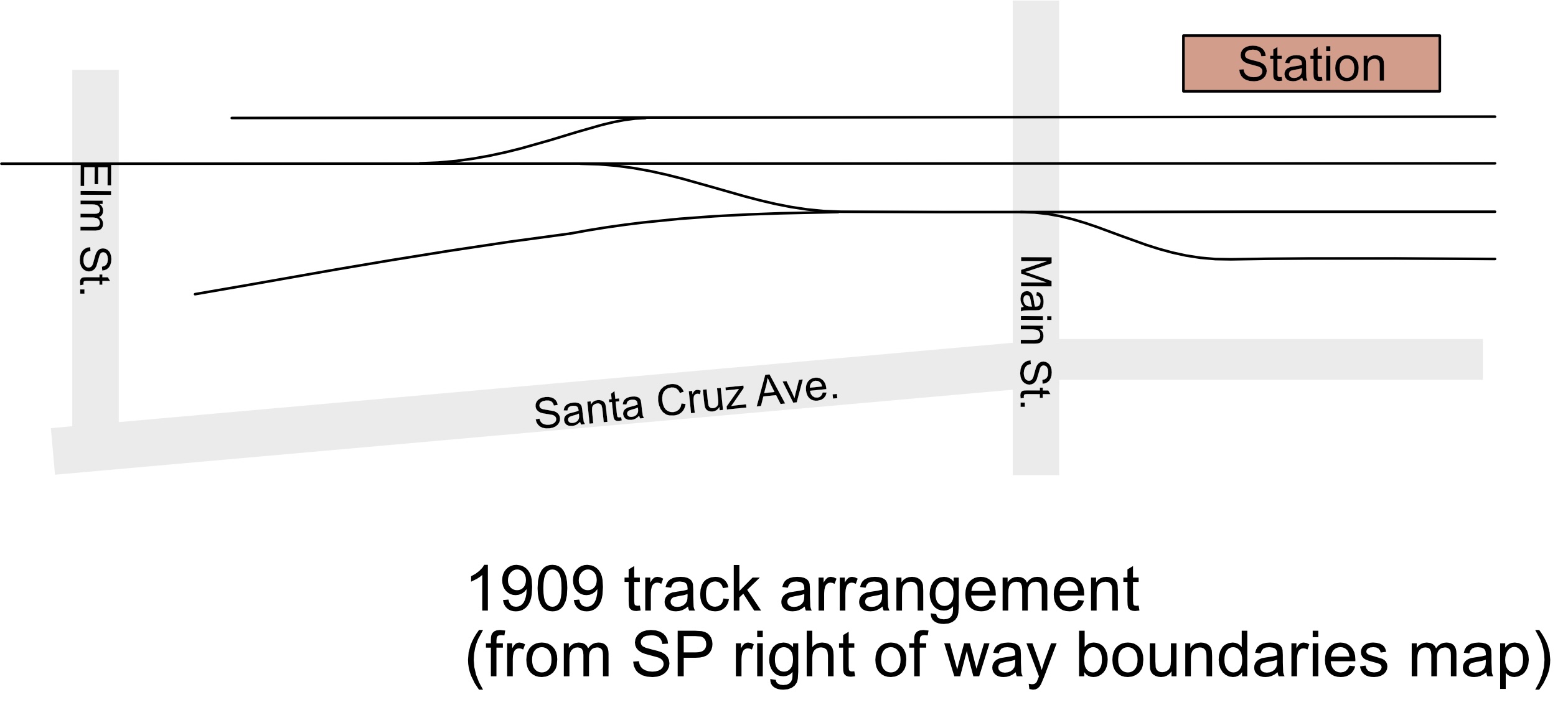
Los Gatos track arrangement, 1909. From Southern Pacific right-of-way boundaries map, California State Railroad Museum collection.

By 1909, we see that the turntable has been removed and replaced with the team track behind the storefronts on Santa Cruz Ave. Apparently, the turntable was unneeded after the end of narrow-gauge operations in the Santa Cruz Mountains. The available map was intended only for showing the right-of-way, so it doesn't show any of the buildings to help us understand how developed Los Gatos was at this time. Interestingly, the lot trackside on the other side of Elm Street has a gas tank for the former coal gas plant - this is where I've placed the ice cream factory.

Los Gatos track arrangement, 1930. From Southern Pacific valuation map, California State Railroad Museum collection.

In 1930, the team track is still present, and the valuation map shows the buildings backing on the team track. Not all the lots were built out - there was a gas station at the corner of Elm and Santa Cruz Ave, showing us Santa Cruz Ave. wasn’t yet the continuous strip of high-end retail it is today. The valuation map still shows the coal gas plant - perhaps I was hasty to put the ice cream factory there?

A final valuation map from 1946 shows a much-reduced Los Gatos. Two of the four sidings have been removed. The team track is also long-removed - a sad ending for a track that started out serving the turntable for the narrow gauge. The photo from 1953 shows the alley behind the buildings on Santa Cruz Ave., hinting at what the area around the team track looked like. It also seems to show that the third siding is still here - perhaps the SP considered it out of service and hadn't removed it.

Alley behind Bank of America, 1953. Charlie Givens photo, from Arcadia Publishing's "Railroads of Los Gatos"

The day to actually start building the Los Gatos scene finally arrived recently - the bare plywood around the team track in Los Gatos finally got on my nerves enough for me to start building. Taking a look at both my past thoughts and what I know about the location, I had a strong idea of what to build. I wanted arow of buildings backing the space behind team track, and giving a place for a detailed scene highlighting that the railroad was a bit hidden from Los Gatos’s commercial strip, but that we’re still in an urban area. The passenger station would be out of scene to the left; passenger trains stopping in Los Gatos will stop anywhere along here. I wanted to capture some of the back-alley feeling from that 1953 photo, but also wanted the area to still appear in use.

Panorama of the finished scene.

Finishing this scene required several building flats. From the 1944 Sanborn map, I see:

  • The leftmost building would be the Bank of America branch, just where the railroad tracks crossed Los Gatos’s Main Street. This was a modern building, appearing around 1928, and matching the style of many other Bank of America buildings in California. It’s a known landmark and an interesting building, and so it’s an important location to include.
  • There would be the backs of several older brick buildings along the alley paralleling the railroad. The first was a low one story building as a store. It held a liquor store in 1950’s. I haven’t been able to track down what was in this back-alley storefront in the 1930’s, but it’s still a valuable place to model - I hadn’t thought there would be storefronts along here until I saw the liquor store in an old photo. That same photo also encouraged me to make a wider alley along tracks. It’s a good building for setting the feel of being in an alley behind the main street, so I’ll make sure to model this.
  • The next was the Masonic Lodge building - two story with high ceilings. (It disappeared and the lot currently has a one story 1950’s store.) I’ll model this as well.
  • Next was another fraternal society - the International Woodsmen of the World - again multi story brick from the 19th century. Still there.) This will complete the row of buildings, and block the view of the backdrop neatly. (Probavblty the Templeman building, built 1921 from reinforced concrete?)
  • There was a series of one story buildings.
  • Finally, there was a gas station at the corner of North Santa Cruz and Elm. I won’t model this, but I will add some fencing.
  • The various brick buildings could be built using whatever scraps of buildings I’ve got in my box, but the Bank of America building deserves a bit better treatment. I'll talk more about Bank of America next time.

Saturday, February 24, 2024

Getting Way Too Excited About Terminal Strips

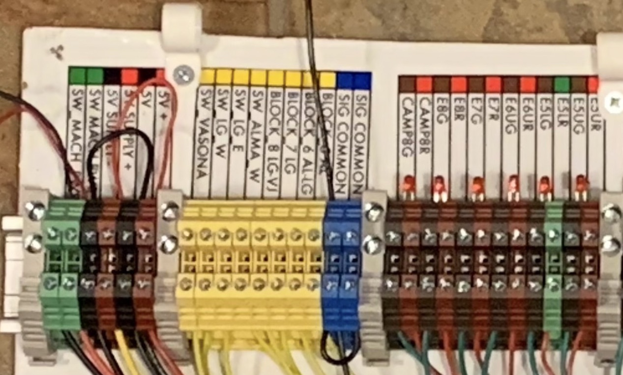
In my last post about replacing the Vasona Branch's signal controller, you might have spotted those odd terminal strips in the pictures of the new signal controller. These are the Dinkle modular terminal strips (the 2.5N size) intended for professional use on industrial controllers and electrical panels. As someone who grew up using the vintage Molex black terminal "barrier" strips from Radio Shack, the terminal strips definitely feel like I’m in a new century of wiring practice. The individual terminals in multiple colors clip together onto a DIN rail, a common mounting bracket for electrical equipment like controllers and circuit breakers.

I found them great for model railroads (as compared with the traditional terminal blocks) for a few reasons:

  • packs more terminals in the same space - about 3/16" per terminal
  • multiple colors so easy to identify terminals and polarity
  • inset test points for safer testing with voltmeter
  • supports adding jumpers for wire-free connections between strips, and two jumpers allowed on any terminal.
  • terminals are covered, so loose wire less likely to touch others.
  • able to reconfigure as wiring changes - possible to pop terminals out of the middle to change colors, or move end clamp blocks to add terminals.

Close-up of the Dinkle 2.5DN terminals showing how they're wired and attached. Terminals are 3/16" wide, wire is 22 gauge.

The price is a bit more than terminal strips from Amazon; they work out to about 30c a terminal compared to 12c a terminal for the classic terminal strips. (They're all a deal compared to $4 each at Radio Shack back in the 1980's!) The other challenge is that getting an assortment of colors requires buying a box of 100 terminals at a time - that’s $30. Getting a good assortment (red, black, green, yellow, blue, white, and brown) requires spending about the same as a plastic locomotive. You’ll also need some of the DIN rail, and some of the end clamp blocks for securing a row of terminals. (For our low voltage uses, you don’t need the thin plastic endcaps to cover the last terminal in a row.) I’m planning on using all I need then selling off spare terminals to someone else if I've got enough unused terminals. I could also imagine having a group of modelers team up and share an assortment.

Jumper with every other pin cut. With these, I could line up a row of alternating green and white terminals for the different switch machine power feeds, then use two jumper barss to connect all to power coming in from a single pair of terminals.

The colored terminals are particularly nice for documenting the wiring. I use different colors for DCC supply vs terminals going out to the tracks (red/white vs red/black), and could color code for signals easily (red/brown and green/brown terminals for “upper” and “lower” signal lights at same location. Sets of terminals can be connected together using jumper bars that fit into the top (and don't interfere with the screw terminals.) 10 terminal jumper bars are available, and can be cut shorter to gang several adjacent terminals together. For the switch motor power, I ended up cutting every other pin from a pair of the jumper bars so that I could feed in the two wires for power to one set of terminals, and have power distributed to all the other pairs simultaneously.

The color coding and labeling also helps me double-check wiring and remember how things are connected years later. When I rewired my DCC track connections using the new terminal strips, I realized I’d mis-connected power from multiple boosters to different stretches of track, probably because I lost track of which terminals were for which section of the railroad. That mistake caused me to melt at least one locomotive when it shorted against a switch but was still getting power from a different booster.

Drawbacks? I needed to use a smaller screwdriver to fit the protected holes for the screw terminals - I couldn’t grab any random home repair screwdriver to turn huge screw heads. The terminals also bent a little bit when pulled by larger wires like solid 12 gauge DCC buses, but work fine for smaller wiring.

One of the rewired panels. It's much easier to understand now!

I’m slowly going around the layout, cleaning up wiring, adding labels, and adding the new terminal strips. I’m very, very happy with these - the terminal strips make it easier for me to understand the wiring even years after I’ve done it, and they make the underside of the layout look neat and organized. I suspect I'll love the terminal strips even more in ten years when I need to figure out a rewiring I did in the distant past.


If you're interested in checking these terminal strips out: I got my Dinkle terminal strip parts from Amazon.com - search for "Dinkle 2.5N". Some sellers offer the components - separate purchases for boxes of 100 of each color terminal, for the end brackets which hold the terminals in place, the DIN rail, and the jumpers. Others offer assortments of 20 terminals of specific colors for common electrical projects such as solar panel controllers. The little assortment was a good way for me to decide the terminal strips were for me. I cut my initial cost when buying full boxes of connectors by just getting a few colors of terminals that I needed for some specific tasks such as re-wiring switch machine power. (I was using just green, white, and yellow for wiring connected to the switch machines.) I later got boxes of the other terminal colors as I rewired areas with other wire colors.

You can also see the terminal strips in use on the layout - the Vasona Branch will be open for tours at the NMRA Pacific Coast Region's 2024 Convention April 24-28, 2024 in San Jose.

Friday, February 23, 2024

Big Changes At Signal Gulch

Semaphores at the east end of Glenwood siding.

When is a model railroad “done”? Some might say it’s when it’s complete - when every scene is detailed and when the trains are running well. Some might say that a model railroad is always being changed, so it’s only “done” when it’s being torn down. I’ll throw out another option - our model railroad is “done” when we’ve confirmed that it’s the right design, when we’ve built enough to know “this is what it’s going to stay like”, and when we’re satisfied with the condition. One easy way to know when we’re satisfied is when we move from building new stuff to having to make big infrastructure changes - replacing a command control system, or changing control panels, or fixing other normally-invisible bits of the layout. If we’ve decided to do some wholesale replacement of some invisible aspect of the layout, that must mean the layout’s lasted long enough for us to need to do big repairs and that we’re happy enough with the layout to do the improvement instead of tearing down and starting a new one.

In my case, replacing the signal system suggests that I’ve done pretty good with this layout.

One of the pain points for my Vasona Branch layout over the last few years has been the signaling system. The real Los Gatos - Santa Cruz branch had automatic block signals (ABS) installed when the line was reconstructed after the 1906 earthquake. (Read Carsten Lundsten’s explanation of SP’s ABS signals here to learn what automatic block signals mean, and how the SP operated them.) The SP assumed the Los Gatos-Santa Cruz line was going to need increased capacity for future San Francisco - Santa Cruz traffic. As they upgraded the line from narrow gauge to standard gauge, they also added the automatic signals to minimize the effort of running trains over the mountains. In the narrow gauge days, keeping two trains off the same track required staffs and other physical tokens, or required explicit train orders to carefully control movements. Having multiple trains follow each other in the same direction was tedious and slow. The automatic block signals got rid of some of this work, allowing railroad crews to know the track ahead was safe to occupy. Note that ABS signals only provide protection, rather than authority. A green signal means that the track ahead is clear, not that your train is allowed to occupy that track. Those train order operators at the stations along the line are still needed to let trains know when they're safe to go.

On the model, the signaling system consists of a bunch of signals placed at intervals along the track, and a signal controller hidden underneath the layout. The controller keeps track of which tracks are occupied using detector circuits and notes which switches might be thrown away from the main line, and sets the ABS signals accordingly. Soon after I’d laid the track on the upper level of the Vasona Branch, I bought a pair of signal controllers - SIC24 (“Signal and Indicator Controllers”) from Team Digital. The SIC24 is a small circuit board with a programmable chip on it; using a DCC programmer (or LocoNet), I could program in signal logic so that if a particular track detector indicated a train was present, or if the switch on either end of a single track was thrown wrong, a signal would go red. The Team Digital boards could also be connected together so that an input on one board could affect a signal output on the other. I used two boards for the needed 16 inputs and 48 outputs. All the signals were within about 10 feet of the SIC24 boards, so I connected all the signals with twisted-pair code 26 phone wire - no need for scattering electronics around the layout.

Old signal controller. Not my best work, but it worked for more than ten years.

The photos shows one of the two SIC24 boards, and the phone cable providing the connection to the other board. This wasn't my neatest job, but it worked. You can see the signal power (large green wires with suitcase connector taps), inputs are yellow wires to the left, and signals are green/white and red/white wires below. I'd realized it was easier to put resistors on all the inputs and outputs here, so they're soldered onto the wires leading to the terminal strips. The odd shape of the plywood is because it's a scrap left over from cutting roadbed for curved track. I was unsure enough about whether the signals would be interesting that I didn't bother to build for good appearances.

The SIC24 boards generally worked well. They “just worked” when the power came on, they had sufficient smarts to run ABS, they were configurable enough to handle a couple of non-standard layouts on the place, and they didn’t require having a computer in the garage with the layout. Over the years, though, the SIC24 boards did start showing problems. One problem is that there’s no way to debug what’s going on; if the indications weren’t making sense, it was hard to diagnose exactly what was happening without attaching a voltmeter to inputs and trying to remember how I’d programmed the boards several years before. I ended up building a little circuit using an Arduino microcontroller board that could listen to the two cards talking and show on a tiny screen which inputs were changing, but that was clunky to use, requiring me to crouch under the layout, plug in the device, and look at a tiny 2" screen to understand what inputs were seen. Over the years, there were also times where it seemed that bits of the signal programming were getting lost. Because I don’t have any Digitrax equipment, reprogramming the cards meant detaching them from the layout, carrying them to a programming track, and attempting to reprogram the whole card from JMRI. I’d then have to reattach the card and see whether the change took - whether the signals now worked correctly. If they didn’t, I had to guess whether I’d mis-programmed the card or if the card was having problems. The several minute delay between making a change and seeing if it worked wasn’t fun, and caused me to give up on several bad signal problem.

I’d finally gotten frustrated enough to decide to replace the fifteen year old signal system a couple years ago. There’s plenty of choices out there, both commercial and home-made. The current NMRA Layout Command Control (LCC) standard defines how to build interoperable signal systems without a central computer. The LCC boards are expected to be scattered around the layout near the signals, then connected via a common bus to communicate. RR-CirKits is selling its Signal LCC and Tower LCC boards that work a lot like the SIC24s I’m currently using. However, they’ve still got the problem that debugging what’s going on requires a computer in the garage, increasing the work required for debugging. It also required me to get up to speed on a new technology, and I’d found some of the online manuals cryptic. Another possibility would be to go in the direction of Bruce Chubb’s centralized CMRI (Computer Model Railroad Interface). CMRI systems have a computer program control the signals, and defines how the different boards scattered under the layout all talk to the central computer.

Both of these are a bit of overkill for me. CMRI seems intended a larger and more complex layout than I have, and has expectations about having a desktop computer present running specific software. LCC has the decentralized and hardcoded logic that I liked from the SIC24, but has similar problems with monitoring and debugging problems, and required me to come up to speed on how LCC worked.

Unfortunately, my day job is as a software engineer, and so whenever I come across “do I buy something to make this happen, or do I just roll my own?”, I’ll often decide to go and build it. That’s often seen as a wasteful choice - why rebuild something that’s already available on the open market? However, for a small home layout, building my own makes more sense. I’ll know the design, know how to debug it when it breaks, and won’t be forced to do upgrades.

In a perfect world, I’d have a tiny Linux computer under the layout controlling the signals, I’d be able to write my own code for controlling the signals, and I’d be able to run a little web server to show the current status of the signals. That’s not a hard thing to do these days; I can buy a Raspberry Pi single board computer for $50. The only question was how to control the signals.

To keep my “no computers in the garage” rule, I chose to build from the Raspberry Pi. This is a little computer that’s the size of a deck of cards, but runs the UNIX operating system and can be logged into and programmed just like a larger computer. It’s easy to hide away, starts up within a minute, and is infinitely configurable. To handle the inputs from sensors on the layout and to power the LEDs for the signals, I chose Model Railroad Control System’s IOX32 boards, small boards with 32 inputs or outputs that can connect to a computer. The IOX boards are built for CMRI based layouts, but the way they talk to the computer, using the standard I2C wiring that lets different devices in a single computer talk, means they can be connected to the Raspberry Pi directly. I ended up getting a Raspberry Pi “hat” - an add-on circuit board that attaches to an expansion port on the Raspberry Pi - to provide the I2C connections. Finally, to help debugging, I bought a small two line display from one of the online electronics companies. This board also talks to the Raspberry Pi using I2C, and can be told to display short messages to help debugging.

This photo shows the new signal controller mounted on plywood. The terminal strips for power, inputs, and outputs is at the top. The Raspberry Pi is the box with the red board in the lower left. The IOX32 boards are to the right of the Raspberry Pi, and the display and 5 volt voltage converter for the IOX32s is to the left of the Raspberry Pi. The crossing wires were needed to match the layout of the terminals on the old and new boards.

As can be seen from the photos, the signal system has a lot of wires going in and out. In order to make the replacement go smoothly, I set up the new system on a plywood board with terminal strips for all the connections, then wrote the software to control the signals and tested it on the bench. This also helped me confirm that the IOX32s could correctly drive the LEDs I use for signaling. More importantly, I made sure the terminal strips roughly matched the layout of the existing board so I could disconnect the old board, detach the old wires, put in the new board with controller, and reattach. I also made a few very good choices to help installation - painting the board with the electronics white for easier viewing under the dark layout, printing up very clear labels indicating the purpose of each terminal, and making sure I had good terminal strips for attaching the connections.

New signal controller in use. LEDs are for signals that aren't yet connected - I've added LEDs on the terminal strip to check their state.

Finally, I took a deep breath, detached and marked the existing cables, pulled out the old controller, and put in the new one. The new system required a bunch of manual work - soldering extensions on too-short wires, changing how some of the detector circuits were powered to ensure a safe common ground between equipment around the layout, and slowly reattached and tested that the signals still worked. This all happened within a couple long days, but it went well with no surprises.

The Raspberry Pi did make it easier to debug. Checking out the existing signals, I found one of my long-lived problems was an incorrectly-attached input for one of the switch positions. I also found some incorrect assumptions in my signal programming, and with a few lines of programming changes was able to get the signals working like the real thing. Debugging is, for now, looking at text logs spewing from a computer program, but I’m looking forward to writing some code to show the layout state on a web page next. I even added a lamp test action at start that flashes all the signals - this makes it easy to double-check that all LEDs are connected and are working.

The biggest drawbacks? The Raspberry Pi does have more complexity. It's a full fledged computer with a boot disk (stored in these modern times on a MicroSD flash memory card.) If the boot drive gets corrupted, then the signals won't work. I’ll need to keep a backup SD card just in case things break.

I must be happy with the Vasona Branch, because I’ve done a big wholesale replacement of the signal system. It took several weeks to get the home-brewed signal controller ready, but all the planning and preparation made swapping the old for the new an incredibly pleasant exercise. I now have much better control over the signal systems, can better understand why it misbehaves, and can quickly fix it so it works correctly in a prototype manner. There’s still lots to do before the layout is fully scenicked, Being willing to do this wholesale fix, though, reminds me how happy I am with the current layout, and how far I’ve come.

Sunday, January 1, 2023

Bay Area Layout Design and Operations Meet: February 3-5, 2023

My favorite model railroad event, the Bay Area Layout Design and Operations meet, is happening this year in Richmond, California, February 3-5, 2023. Like always, the meet's a mix of talks about design and operation, layout visits, and opportunities to try model railroad operations on layouts in the Bay Area. Friday will have a tour of the real Richmond Pacific industrial railroad. Saturday's talks will be at the Golden State Model Railroad Museum at Point Richmond. We'll get to tour layouts in the East Bay on Saturday night. Operating sessions at local model railroads will be on Sunday. Like last year, you can also attend virtually if you're not in the Bay Area or want to enjoy the presentations from your home.

Get more information at www.bayldops.com. You must get tickets in advance at EventBrite. In-person tickets include a boxed lunch. Virtual tickets give you access to watch the presentations and ask questions via a Zoom video conference. In-person tickets also include the Zoom link in case you decide not to go up to Richmond.

I love the Layout Design and Operations meet because it pulls together a fun group of folks: interested in modeling specific locations, railroad history, imitating the real railroads' operating practices, and just interested in understanding what the real railroads were about. It's also a great meet if you're curious about any of these topics. The invites to operate on local model railroads got me interested in model railroad operations, and helped me understand the differences between running trains on my own versus working with a dozen other people to get trains moving on a large layout. Like past years, we'll also offer layout design and operations consulting. If you're considering a new layout, or thinking about operations on an existing layout, you can sign up for time to talk with others about what you're building and what options you might consider.

I'm planning to have the Vasona Branch open for a Sunday operating session, so if you're interested in visiting and joining in, sign up for the meet and put the Vasona Branch down as one of your choices for an ops session!

Hope to see you there!

Saturday, September 12, 2020

Rebuilding Glenwood

A string of maintenance-of-way gondolas heads uphill.

Like I mentioned last time, long-suffering Glenwood got some serious rework recently. I had some good reasons to finally return to Glenwood. The ProRail invitational was going to be in San Jose in April (before COVID-19), and the visitors from around the US deserved to see the layout at its best. I needed a distraction from work, and wanted some projects that could fill a weekend.

I also had several years of pent-up frustration waiting to be unleashed. Glenwood’s also an old part of my layout; I laid the track on the upper level about two years into the layout, and roughed in some scenery. The model doesn’t accurately capture the real location. It’s not up to my later standards for prototype scenes. It's not eye-catching enough to be a focal point for the layout. Glenwood’s also in a darker corner of the layout, and in a location that’s not central to model railroad operations, so it’s never gotten a lot of scrutiny. Glenwood deserved better.

But being generically dissatisfied is one thing; I need a list of things to fix. Let’s run through the problems at Glenwood.

Glenwood before the rework.

Problems with Glenwood:

  • The road’s unrealistic, just badly-levelled Sculptamold on foam scenery, with sheer drops and no shoulders.
  • The building just above the tracks isn’t prototypical; although there was a small house there, the building on stilts doesn’t match the location, nor does it look realistic for the 1920’s. It also draws attention away from the prototype portions of the scene, hiding that great curve into the cut and tunnel.
  • I'd built a station building, but it’s a coarse plastic model. There’s none of the maintenance of way buildings or outbuildings seen on the maps.
  • The grassy hillside doesn’t quite match reality; prototype photos show more trees. The grassy hillside doesn't hide the unprototypical terrain, and misses the chance for trees as a view block to frame the scene.

So my plans? Tear out the hillside, improve the tunnel entrance, make the scene more realistic overall, and detail the station area.

Redoing Scenery

Step one was ripping out a bunch of bad scenery - taking out the hillside, the cut, and the house-on-stilts.

Before any of that, I took a pass at a bunch of other unfinished business. The turnout in front of the tunnel was a frequent derailment site. I ripped out the track, leveled it out with spackle, and relaid the track. The old Tortoise switch machine was a problem; it stuck out too far below the bottom of the deck, and was difficult to adjust. I swapped it out for one of the tiny MP-5 switch machines. I also took this opportunity to check on the track in the tunnel, pulling up even more track, using spackle to again ensure the roadbed was as level as possible, laid the track better, and sealed in the tunnel so that stray light didn’t ruin the illusion of a tunnel through a mountain.

With the track done, I hit the rough scenery.

The new hillside started out with the focal point: the road climbing over the hill and curving around the top of the tunnel portal. This road’s actually the Glenwood Highway, the first paved road across the Santa Cruz Mountains, and first state highway over the mountains. The Glenwood Highway, built between 1912 and 1921, split off from the current Highway 17 on the ridge between Glenwood and Laurel, dropped down into the Bean Creek canyon, then headed through Glenwood towards Scotts Valley. The concrete road, 15 to 17 feet wide, had banked curves and oiled shoulders. It was the height of modern highway design. When the Glenwood Highway was widened in 1939, the town wasn’t big enough for the highway and the railroad; the SP lost that battle, and the depot was torn down to encourage more space for cars. The current route of Highway 17 later won out, but the jazz-era Glenwood Highway still remains if you drive through Glenwood today.

Road during rework.

Road after rework.

Old photos show the key details of the Glenwood Highway: precise curves and straightaways, the odd slalom around the top of the tunnel portal, and an even descent. I followed an approach I’d used elsewhere. I’d started by roughing out scenery to match the rough slope I wanted, and tore out as much of the old road as I could. As I’ve done elsewhere, I used 1/16” styrene sheet for the roadway, scribed with expansion lines. I cut the styrene at the workbench so I made sure curves were accurate and straightaways were smooth. I glued the sheet to the scenery with Liquid Nails contact cement, and used weights and straight lumber to keep the road flat until it dried. Once the road was glued in place, I used Sculptamold and spackle to finish the fills and shoulders.

Time for detailing the scene.

SP 84 heading out of Glenwood tunnel towards Santa Cruz.

SP 31 coming out of tunnel.

This photo of train 84 coming out of the tunnel shows that the bottom of the canyon had a bunch of pine trees in the 1920's. I'd always intended to capture scenes like this: the conifers in the canyon, oak trees higher up, and the privacy screen of trees between the highway and the railroad tracks. Rearranging the hillside and roadway helped this a bit. Filling in undergrowth and deciduous trees is easy; I've been using either Supertrees or Woodland Scenics Fine-Leaf Foilage. The redwoods and other conifers were more of a problem. I'd covered the hillside around Wrights with Woodland Scenics conifers, but I'd found these slow and tedious to build. I'd started trying to do the same at Glenwood, but eventually figured out that gluing tufts of sponge to the plastic armatures was not how I wanted to spend my hobby hours. Luckily, I'd gone to a model railroad train show right before COVID-19 struck. Grand Central Gems out of San Diego was there with their pre-made trees; I bought a few bags of tall pines, and loved how quickly I managed to get the scene finished. I bought a couple more bags later, quickly filling the hillside. I've always been cheap and unwilling to buy pre-made trees, but spending less than a locomotive to get this scene finished was worth it. With enough trees, it was also easy to give the look of separate areas of fields separated by tree lines. Static grass and a barbed wire fence made of wood posts and fishing line completed the scene.

Turntable:

In the earliest track plans for the Vasona Branch, I’d sketched in a location for the pit for the former South Pacific Coast turntable. Glenwood had been a key spot for narrow gauge lumber traffic; many short trains would carry lumber up to Glenwood; from here, a single engine could pull a longer train through the summit tunnel and down to the Santa Clara Valley. One of Bruce MacGregor’s South Pacific Coast books mentioned the filled-in turntable, so I added it to the track plan as an interesting bit of history. I’d cut a half-moon hole in the homesite for the turntable at a convenient location when I first laid track.

In the last episode, I mentioned finding the valuation maps and spotting the actual location. There were actually two turntables. The one at north end of town that apparently was filled in and tracked over during standard gauge times. The other turntable was at the far end of the siding, hanging over creek edge. Neither matched my guess when I'd first sketched the track plan.

I’d already cut the notch in the layout for the turntable in… oh, 2005, and wasn’t up to moving it. Stories claim the turntable was mostly filled in, but I took the existing hole, added stained balsa wood around to support it, added some debris on the bottom, and called it a day. It'll be a good location to throw whatever clutter I happen to have kicking around.

Glenwood Station:

I scratch built the Glenwood depot using some existing plans, and inference from photos. Gary Cavaglia published plans for the Glenwood depot in the March/April 2003 Narrow Gauge and Short Line Gazette. His drawing laid out the original narrow gauge depot building from the 1870's. That building contained a waiting room and tiny baggage area, and was completely sided in shiplap siding. All the photos from the times I model show a different structure. Apparently, the station was extended some time before standard gauging. The 1920's station extended the office portion of the station, built on a long addition for baggage and freight, and added a large raised freight platform matching SP's standard station designs. The station, however, kept many of the details seen in other SPC depots in Alviso, Agnews, Alma, and Wrights: similar doors, roof supports, and roof peak decorations.

Cavaglia’s drawings of the depot gave me the rough shape: walls were 12 feet tall; the gable peaked at 17 feet, and end walls were 14 feet wide. The drawings also laid out the rough sides of the passenger section. During the reconstruction, a door moved; I assumed the windows stayed in the same location. Using these measurements and various expectations (doors 30” wide, windows three feet off the ground) I could infer other measurements. The waiting room originally had two windows with a door between; later photos show a solid wall and a door to the right. Apparently, the reconstruction kept windows in the same locations but blocked up the original door location.

The later extension to the freight side of the depot was board-and-batten which made guessing at lengths easier - the battens appeared to be spaced 12” apart, so I could make guesses about the overall length of the extension. I sized the freight dock to the space available on the layout, rather than the size of the prototype’s.

SketchUp model of Glenwood Station

I sketched the whole model in SketchUp because I could do so quickly - I already had 3d models for the SP-style windows, so putting together the rough shape was fast. Once I had a rough model, I could compare it to photos and confirm that it looked about right. I could have done the same with pencil sketches or with a cardboard model.

I built the model using sheet styrene, window and door castings from my hobby stash, and vacuum-formed shingle material from Plastruct. I was lucky that all the supplies were already in my hobby stash, for I started the model just as the Covid-19 shelter-in-place started here in Silicon Valley. Like many of the SP stations I built, I used the Grandt Line 5031 windows (12 pane double-hung windows) to match the main windows, and the narrower Grandt Line 5029 windows for the sides of the operator’s bay. (I use those windows a lot, so my box-of-windows-for-projects usually has some on-hand.) I scratchbuilt the freight doors from styrene sheet. It doesn’t take a lot of styrene to be able to knock off one of these models; I usually keep a couple sheets of board-and-batten material, a couple sheets of shiplap, and then strip styrene in 1x4, 6x6, 2x6, and 2x8 dimensions, and that’s all that’s needed for most buildings. I also keep large sheets of 1/16” sheet styrene from TAP Plastics because it’s cheap and useful for bases or backing support. I also had some very beefy .156 x .250 sticks of styrene; these turned out to be really handy for building up a base for the loading dock. I could have done the same with Plexiglas, but that would have required shopping, and also required using power tools in the garage. Building from styrene let me build quickly with just a #11 X-acto knife, a square, and a straightedge.

Overall, scratch building a model like this is quick - probably a week of evenings including design and painting. The worst part is cutting out the window openings. If you haven’t tried scratch building, find some simple building, get $25 in plastic from your favorite hobby store, and start cutting!

Maintenance of Way Buildings

Who was around in Glenwood? Even with the large station, Glenwood never attracted the business one would expect; it didn’t become a wine center, didn’t have a major lumber industry, never attracted farmers. The August 1916 Southern Pacific payroll on ancestry.com showed Campbell station had an agent, warehouseman, and clerk, and apparently had a part time “fruit checker”. Wrights had an agent and warehouseman in their little hamlet. Meanwhile, Glenwood’s large station only had Alfred Feldt, operator, making $80 a month. Feldt eventually moved to San Lucas; in 1920, Edom N. Davis had the agent role. The abandonment proceedings in 1939 declared that only 196 people lived in the Glenwood area.

The section gang was a big chunk of that population during the teens and twenties. 1916 payroll records show six laborers and a foreman in Glenwood, reminding us that the section housing and work sheds deserve to be prominent. The August 1916 records show similar section crews at Campbell, Los Gatos, Wright, and Santa Cruz. The 1916 crew included V. Simoni as foreman, P. Simoni as watchman (perhaps for the tunnel), and G. Simi, M. Mariani, J. Jilla, A. Scarponei, U. Balleroni, and G. Berlacgua on the crew. The 1920 census showed a similar crowd: Benjamin Capp, Vigellio Elli, Toni Gianti, G. Luciano, Joseph Menta, Sam Chientilli, and Angelo Fideli. The railroad apparently was a good gig for the new immigrants. A separate continent of Mexican workers listed their occupation as wood choppers in the same census pages. Valuation maps don't show housing for the workers, but a few 1920's photos show what appear to be bunk cars on the siding next to the tunnel. Twenty years later, a Vernon Sappers photo of the Felton depot in 1935 shows maintenance of way bunk cars on the siding behind the Felton station, suggesting the maintenance of way workers moved closer to the bright lights of civilization.

I'd hoped on hinting at the folks who worked in Glenwood. I've got some bunk car models (care of Jason Hill of Owl Mountain Models fame), but I hoped I could include the section house where the foreman lived. Unfortunately, I'd started figuring out a location too late - I already had the station and an Atlas water tank in their rough locations. Unfortunately, I couldn't figure out an arrangement that didn't appear too crowded. Instead, I added a tool house built from a A&LW Lines laser-cut kit, and an outhouse next to a privacy fence.

Scenery improved? Check. Unrealistic buildings removed? Check. Prototype station in place? Check. Tons of trees? Check. Glenwood was always a place I modeled because I wanted to capture the real look - the curve into the tunnel, the redwoods, and the interaction of the new highway and the old railroad. It’s now got that look I intended.