Monday, November 10, 2014

Next Project Sneak Preview: Hart Convertible Gondola (G-50-3)

I've already shown pictures of my 3d-printed SP CS-35A flat cars. I've also hinted at my F-50-4 models - 1915-era flat cars with very thin decks. I've printed some of those flat cars; they're visible on the video that went along with the CS-35A article, but they're also a pain to decal because the prototype lettering looked an unreadable four inches high. I'm feeling pretty good about both these models, and happy to be on my way to having some flat cars for lumber service on the Vasona Branch.

So what's next? Looks like it's going to be the patented Hart Convertible gondolas, known to the Southern Pacific bean counters as the G-50-4. Harry Hart of the Rogers Ballast Car Company designed a gondola that could be used for different jobs repairing a railroad's maintenance-of-way. Doors on the side of the car open to dump fill dirt out. The floor hinges up to open a hopper area to dump ballast between the rails. The end bulkheads could be moved towards the center of the car to keep ballast near the hopper, or removed so that rail or other heavy material could be dragged off the end of the car. SP had around 700 of these cars, which existed into the 1940's.

This has been a pain to print. It's a forty-foot car, so it won't print flat on the Form One. Printing the model tipped up allowed the model to print, but the support material to hold the half-printed car used a ton of resin. I also had problems with dirty mirrors over a few weeks that resulted in several failed attempts and a lot of wasted resin. But after finally identifying the problem and cleaning the mirrors, I've been much happier. I've found that I can print the cars vertically with pretty good success. Those successes also mean that it's possible to print 50 foot HO freight cars on the Form One.

And the detail's mighty sweet, too - the castings for holding the door print cleanly, as do the underbody trusses and hopper assembly.

I'll tell more later - I'm still working on this. I've just finished a second print of this model with correct strapping for the hinged doors, hinged metal apron to cover the spaces between cars, room for the brake wheel on a corner, and a mount on the side of the car for the brake cylinder. However, this photo at proves that I'm actually printing non-trivial 40 foot cars.

3D Printing's Killer App: Printing Tons of Human Figures?

Human figures are a big problem for model railroads. There's few sources for the figures, they're often drawn to resemble 1970's European figures (because of the primary vendor). There's few figures available for the uncommon modeling scales. But we need those human figures to keep our scenes look like we're modeling a live, active world, and not some post-neutron-bomb apocalyptic scene. (Kids, if you don't know what a neutron bomb is, ask your parents. Or ask Google.)

One of my big surprises for the Form One is how beautifully it does tiny figures. showed some examples soon after I got the printer. This latest photo shows the results from letting the printer do lots of multiple figures over a couple evenings last week - about forty figures in four different poses.

The figures are all from the Great Fredini, who has scanned attendees at the 2013 World MakerFaire New York and other events on the East Coast. Here, I'm printing four models: MichaelZ, Sir Makealot, Kathy C., and Joe and his kids.

After making do with 1970's German figures from Preiser or random injection molded figures from unknown manufacturers, there's two things very special about these figures. First, they're very detailed - you can see some of the details of the person's face and hair. That's detail you usually don't see in injection molded figures. Second, these figures look like real Americans, because, well, they are. If you're not modeling a world filled with wasp-waisted women in tea dresses and conservatively dressed men from the Preiser line, these figures look much more suited for a modern American layout: people who are normal sized for America, or potentially wearing football jerseys, or t-shirts, or shorts and flip-flops. These models aren't perfect for me and my 1930's layout, but I appreciate that they look *right* for a modern layout.

These 3d models don't fully replace the injection molded people. It takes time and an expensive printer to make the figures. These models are skewed towards modern-day figures, so you're not going to be able to get a full set of 1940's figures any time soon. Still, it's going to make filling a scene with realistic people much easier for our modern modelers.

Technical details: I could easily print about 9 figures in HO scale in an hour and a half, printing at 0.050 mm (0.002 inch) layer resolution. The print time was driven mostly by the time to raise the platform; I probably could have printed 16 or 25 figures with little increase in print time. My only constraint was just getting the software to handle more figures; these models are very detailed, so just trying to do the slicing match on 25 figures brought my old laptop to its knees. Cutting the details on these models would have made printing 25 - or 75 - quite feasible. And the great thing, of course, is that none of this is HO specific. If you wanted S scale figures, or TT scale figures, or 1:43.5 figures to match your true O scale models, you can print all the human figures you need for your layout. So with a long weekend, I'd have the figures for a pretty big mob.

Fredini's models were scanned using a Microsoft Kinect sensor, a home-made scanning rig, and some off-the-shelf software for converting the Kinect's data into a three-dee model. He's continuing to scan folks at various events, and his collection of 3d models of visitors to his booth at Coney Island is another great source of figures for your model layout. I'm waiting to see a similar scanning booth at model railroad shows.

Tuesday, October 21, 2014

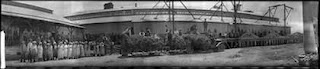
Setting the Scene: How the People, the Equipment, and the Containers Describe an Industry

So here’s a fun photo from the John C. Gordon collection at San Jose State: a photo of the California Packing Corporation’s plant #21 at Milpitas. The photo probably dates from the twenties or early thirties, I expect, and gives a lot of detail about both the workforce and the plant.

Now, there’s a bunch of interesting bits worth examining in this photo.

The workforce looks like it’s half men and half women, with the men primarily in coveralls and women primarily in white. There’s no obvious management; there’s a couple guys who look cleaner than the others - one in a jacket, and a couple with shirts and pants - but you don’t see the guys in suits or the owners like you’ll often see in the photos of a cannery. The men mostly look anglo; although there’s a few faces that look Italian or Portuguese, most look anglo. The women, however, seem to go more for that southern European look - I’m seeing a lot of faces from old family photos here.

Next: what’s with those cranes, and what’s that wilted stuff that’s on the truck and its attached wagon? My initial guess was that it’s bringing in some sort of plant where processing the crop in the field is too labor-intensive. One possibility is that they’re some tiny crop - maybe peas. Or maybe they’re the tops of plants that went to seed. There’s mention that there were seed farms in Milpitas, so perhaps Del Monte was letting the plants flower, cutting them down, then threshing the seeds out in the plant here? The cranes might be used for bringing in the whole plant - the whole plant would be cut down in the field, brought here to the packing house. You can also see some sort of hoppers located in the wall along the right loading dock, with wheelbarrow-sized openings to pour something into.

While we’re at it, how about that truck and trailer, and those cool wooden wagon wheels?

And finally, if you look along the loading docks, you’ll see an interesting mix of containers. Towards the center of the photo, you’ll see a stack of what look like trays, and then, just to the left, you’ll see some shiny objects. That’s tin cans, fresh from the can factory. They’re stacked up, with wooden sheets separating each layer of cans. Although there’s a lot of cans there, the pile of the separating trays, off to the right is even more impressive, suggesting it’s been a busy canning season.

Now I’ve never thought much about how cans get to the cannery. I’ve heard my dad’s story of a summer spent at either the Hunts cannery in Hayward or the Del Monte plant in San Leandro grabbing cans out of boxcars with a long stick with metal fingers spaced out a can’s width apart. That was in the 1950’s. It looks like in these earlier times - or at this lower-volume cannery - the cans arrived in a more primitive way.

Then you’ll see lug boxes for bringing in the crop, and a sign above the door that I’m sure says “POSITIVELY NO SMOKING”, and some sacks of something. And finally, at the far left, some Del Monte product boxes, all labeled “SUGAR PEAS”.

And the mystery is solved. The Milpitas plant was canning sugar peas on this day. The pea plants got cut down in the field and pitchforked up onto wagons, then hauled to the cannery where the cranes tipped the wagons and their loads onto the loading dock. The hoppers are actually the input side of the viners, which would strip the pods from the vines and the peas from the pods. The peas would go in the lug boxes, then be carried into the cannery for cooking and canning. The cans are there on the dock ready to put into the machinery. When the product was canned, the result would go in the nice wooden crates at the left.

There’s even a video confirming this; Del Monte filmed the action at a pea cannery in 1939, and that’s on YouTube. The 8 minute mark shows the peas being harvested; the 10 minute mark shows the pea vines being tossed into the viner.

And we’re learning all that from just the stuff out on the loading docks.

Now, as a model railroader trying to detail cannery scenes, what we’ve learned from this photo really highlights how the clutter on a model helps a viewer understand what’s happening. Being able to see the raw material (the pea vines and cans), the finished products (cases of canned peas), and the workers hints at what’s going on here, and helps the photo - or the model - set a story.

Let’s Build Containers!

Normally, telling a story through those details on a model railroad either takes a lot of work or a fair amount of cash. Take sacks, for example. A prune packing house should be overrun will full sacks of prunes around September, for the local orchardists bring in their crop bagged. If you've got a prune packing house on your layout (and I've got three), then you need a lot of very tiny HO scale sacks of prunes. There's normally two solutions: make them, or buy them. I've made sacks from Fimo clay, but it's a slow process. You roll out a long string of clay, chop it into pieces, flatten it a bit, shape, and bake. (Interesting bit of trivia: Fimo polymer clay costs $3.59 for 50cc of material, or around seven cents a cubic centimeter. It makes the resin for the laser printer at fifteen cents a cubic centimeter seem pretty affordable.) Getting metal castings of filled sacks is possible - the military modelers love them for making foxholes and protected positions. But getting a ton of sacks involves spending real money.

Boxes and crates have the same problem - there's store-bought ones, but they tend to be in a few designs, and you'll never find more than a few for sale at a time. They're also hard to make by hand; either you make a lot of fiddly details and glue them together, or figure out a way to mock up entire stacks or rows of boxes with a printed image or some artfully placed scribe lines. Boxes are also hard to get right because of the precise shapes. The sacks can have mistakes and look mostly correct, but if your scribe lines don't make all the boxes the same size, then you've spoiled the illusion.

And then there's other containers that you can't buy. You've already seen my drying flats - a detail that's both impossible to buy commercially and a pain to build from scratch. Empty boxes (such as field lugs) aren't available as castings, though Ken Harstine sells some beautiful stacks of fruit lugs on Shapeways.

And all of this makes 3d printing a great solution for printing large numbers of detailed containers for a particular scene. The 3d printer is great for doing runs of lots of duplicate items to fill out a scene. Digital models make it easy to do variations - this stack is 6 boxes high, that one's seven, and the other has one slightly out of line.

And the best thing is that 3d printing is a great way for those little details you wouldn't necessarily see across the US, and thus aren't popular enough for the manufacturers. Remember those stacks of empty cans? I've never seen those on a store shelf before, but with some judicious 3d drawing, I can make some stacks for my own canneries.

Photo from the John C. Gordon panoramic photo collection at San Jose State University. They also have the regular John C. Gordon collection which has a bunch of commercial scenes from San Jose over the years.

Sunday, October 19, 2014

Progress on San Carlos Street

J.S. Roberts, 1934

The San Carlos Street viaduct is one of the key scenes for the Vasona Branch. The SP paid for the viaduct in the early 1930's as a last step before main line tracks could be removed from Fourth Street and the business district of San Jose. The viaduct jumps over the former South Pacific Coast tracks heading towards Campbell and Los Gatos, but, more importantly, it provided space for the new mainline tracks to head under the viaduct and around town.

As a model, the viaduct's important; it's a well-known location around these parts, it adds interest to a boring turn, separates the West San Jose and Auzerais Street scenes, and has the potential to add clutter and action. Sadly, the area's not gotten much love; I've been collecting photos and ideas for reworking this area, and I've been building a new version of the packing house just under the viaduct, but I'm finally getting some modeling done.

Here's photos of the scene after a busy week. The packing house is in place (with some resin-cast prune boxes on the platform). The sweet looking CalPak sign text is a guess, but there's a sign with similar outlines from the back in one of the photographs of the area. The bridge supports almost match the actual bridge - a mix of two-legged piers (for piers that weren't liable to be damaged), partial walls (near railroad tracks), and full walls (for the Dupont Street underpass I'm not modeling).

The storm drain pipe with water was an afterthought, and a nice way to quickly add a bit of interest and action to the scene.


John S. Roberts photo taken from a John C. Gordon photo in the San Jose State University special collection.

Tuesday, September 30, 2014

Sunday, September 21, 2014

Printing a Freight Car: Southern Pacific CS-35A Flat Car

I’ll admit it. I’m not a freight car modeler. Sure, I’ve had an appreciation for appropriate freight cars from my era, and I’ve built a lot of resin kits for the Vasona Branch. But I’m not one of those folks who could argue the difference between the different patent pressed-car ends, or could tell you what percentage of B-50-14 boxcars had Bosendorfer side doors, or would argue about the appropriate underframe for a stock car. But, hey, all that goes out the door when I decide to print freight cars on the 3d printer.

My list of potential 3d-printer projects has always included a few freight cars. As popular as the Southern Pacific may be, modeling the 1930’s means building a lot of resin kits, searching eBay for old kits, or finding a lot of stand-ins. One example would be the Hart convertible gondolas, frequently used for dumping ballast on railroad tracks. Another would be flat cars - Southern Pacific’s 1930-era flat cars look much more fragile than the typical 1950’s plastic flat car kit that’s available, and tended to have a very specific look. More importantly, I needed flat cars for the Vasona Branch - lumber coming from the sawmill at Laurel needed to come down the hill to the lumberyard at Auzerais St.

I’d hoped my first-generation Makerbot was going to help me with freight cars, but it couldn’t print something that looked good at HO scale - the layers in the plastic were too obvious. The Makerbot could only print within a 4 inch cube - not big enough for even a smaller flatcar. The Form One, though, was getting big enough. At 125 mm x 125 mm x 165 mm, the printer could print a 36 foot freight car diagonally, or a longer car if I tilted it up on end. So, soon after I’d gotten the Form One up and printing, I tried a couple flat cars. Here’s the details on that first flat car.

The Prototype: Southern Pacific CS-35A Flat Car

In 1903, the Southern Pacific decided to experiment with freight cars built completely of steel. Two plans appeared that year: the CS-35 car (36 feet long with 40 ton capacity) and the CS-35A car (40 feet long, 40 tons). Both these CS (Common Standard) cars represented first attempts at a flat car with a steel under frame: a pair of 15 inch I-beams along the center, and pressed steel sides tied together by a 19 inch deep C-channel. The two designs were apparently in a bake-off; both designs date from October 1903, but only the CS-35A got the green light. SP had 1,000 of the 40 foot cars built by the Pressed Steel Car Co. in Chicago.

The CS-35A, designed during the Harriman era, differed from later flatcars such as the F-50-2 by having only nine stake pockets on each side compared to eleven or twelve on later cars. Other spotting features was the lack of rivets on the bottom edge (unnecessary in the stamped forms of the early cars, but needed in the fabricated side frames of later cars) and twelve rivets on the side at each truck bolster.

These flat cars definitely looked different from the other standard SP freight cars - relatively shallow sides, no truss rods, and longer than most of SP’s flat cars. Compared with modern freight cars, they look positively wispy and fragile. They also lasted a long time, with Tony Thompson’s SP Freight Cars book showing the cars still in common use in the 1920’s, both for revenue service and for maintenance.

Of course, there’s no models of the CS-35A available, whether as a resin kit or plastic model, so it was a great first try for 3d printing.

The Model

The first question was how to build the model - do I try to print the whole freight car in a single piece? I’d seen models on Shapeways where only the metal parts were 3d printed; the wooden deck for the flat car was done with laser cut wood. That seemed great; the wood deck would be more realistic, and I could print the model upside down on the build platform. (That didn’t work; more later.) I tried doing a couple models where only the frame of the flat car was printed, with big openings below. That didn’t work - the printed piece ended up being too thin to print, and wasn’t strong enough to survive removal. I ended up building the model so the top was solid and 6mm thick; the wood deck would be glued onto that surface.

I did the initial drawing for the CS-35 in SketchUp. I started out sketching the rough shape, extruded it as a 6 scale inch thick slab, then started adding details - first the frame and ends, then more and more detail. I scaled the sides so they were 6 inches thick and printed more reliably. For details - stake pockets and patterns of rivets - I often drew the objects in a separate SketchUp model, then made the object into a group and pasted copies into the final model. I learned that 1” diameter cylinders, 1 inch high, made great rivets. I also marked the holes for grab irons by drawing a 1.5 inch diameter hole.

There were also details I didn’t model. I didn’t add brake gear to my initial model. I planned on using wire grab irons, and grabbed brake wheels from my scrap box. I did need to model the brake cylinder for the car; it’s obvious on all the real photos I’ve seen. I started using the Tichy Train Group’s K Brake kit, and bought a half dozen at my local model railroad shop, but found I was only using the brake cylinder. I ended up building a 3d model for the brake cylinder, and printing the brake cylinder myself.

One of my other surprises when building this was the question of what exactly to build. Any model has compromises - I might not want to add all details, or I might need to change a dimension, or I might tweak the model to fit a model railroad coupler. Figuring out these differences between the model and the real thing is the hard part of making a model, whether by hand, with a 3d printer, or when designing an injection-molded kit. For the CS-35A, I had to decide whether to add some of the underbody beams and braces (no), or what detail to add to the ends (minimal.) I also had to choose between scale dimensions and a reliably-printing model. I ended up making the center I-beam much thicker than in real life so it would print more reliably. Instead of 1 inch, I made all the walls 2 inches thick. I also drew it with slopes inside the I so there wasn’t a difficult transition from thin to full-width.

Flat car and support structure. Support structure holds car at 30 degree angle to avoid any horizontal slice through the middle being too large.

I also had hiccups. I had problems printing the final model because of extra hidden faces; I used Netfabb Basic to clean up the models and prepare them for printing. Even that didn’t work reliably. Because of the Form One’s resolution, making a “watertight” model (no holes or gaps between faces) was critical. On the Makerbot, the low resolution meant holes would usually be ignored when breaking the model into layers. With the tinier resolution, even a small hole could convince the Form One software that you intended the model to actually be hollow. I also found that pieces thinner than 2 scale inches (0.020 inches, or 0.5mm) didn’t print reliably. (The design rules from Shapeways for their frosted ultra detail material have similar limitations.) I found I couldn’t print the freight cars flat on the build surface either without layers failing to bond. Formlabs, the maker of the printer, suggests that large flat prints be done at an angle so that any individual printing layer doesn’t cover a large area. Doing so gave me more reliable printing, but doubled print time. I also found I needed to be careful about cleaning the model - I’d been leaving the finished prints in direct sun to cure, but had problems with warping. Keeping time in the sun short, and making sure both sides were exposed to the sun helped limit warping.

Initial model. Note messed up corner caused by deformation when printing near edge. The other cars weren't this bad, but all cars printed with the long edge tipped had a bit of deformation.

The overall process for printing the flat cars was something like this. First, I’d print a couple models over a day or two. Like all the 3d models, I’d pull them out of the printers, remove them from the build platform, and soak them in isopropyl alcohol to wash away the extra resin. I’d remove the support structure added to print the model, then leave the models in the sun for 10-20 minutes on a side. Another day, I’d spray paint the models (Scalecoat boxcar red in a spray can). I’d drill out holes for the screws holding on the trucks and couplers, then attach both with plastic screws, and cut the screws off flush with the top surface. I’d then add a wood deck using individual 2x8 wood boards stained with india ink and alcohol, gluing them on with contact cement. I decaled the cars, then then drilled holes for wires representing grab irons and superglue them in place and touched up the paint on the grab irons. A final spray of Dullcote sealed the decals onto the model.

I made a couple embarrassing mistakes with the model. On my first try, I used the plans in Tony Thompson’s “Southern Pacific Freight Cars” book to build the CS-35 36 foot car. That model turned out well (and the 3d model is available on Thingiverse). When I went to decal the model, I looked for the car numbers for the 36 foot cars… and realized there were none listed - SP never built any. I'd been printing the Loch Ness Monster of SP flatcars.

To correct my mistake, I stretched the design out to make a 40 foot car. In SketchUp, this wasn't too challenging; I'd select the portions of the flat car from the bolster out, then use the move tool to drag these out the appropriate distance. After I printed a few of the longer cars, I compared them against photos, and realized the model didn’t look right - the wheels were set closer to the center of the cars. The CS-35A looked a bit like the ends of the cars were unsupported. I went back to SketchUp, and moved the truck bolsters in.

The final model requires about 15 cubic centimeters of resin and prints in three and a half hours. The resin cost about 15 cents a cubic centimeter, and about half gets lost during printing and cleaning, so we’re talking about $3 in resin per freight car. Compared to Shapeways, which would charge around $30 for a similar part, it’s not a bad deal. On the other hand, I went through a lot of prints for testing - probably 10 to 12 pieces. Once I got the design and printing settings done, it was easy to print more flat car castings on demand.

I still have some minor problems with warping, and the arrangement of the model usually causes one corner to be bent in a bit. Both they’re still fine models,and I’ll be able to make some reasonable 1930’s flat cars for my layout quickly. One potentially big problem is that the models are very light - only about 1.5 ounces with trucks and couplers, much lighter than the recommended 3.5 ounces. I’m planning to either add weight to the loads on the flatcars, or add some lead sheeting in parts of the model.

The Decals I printed and decaled one of the “wrong truck spacing” cars using a mix of leftover details; that process was amazingly painful. I tried finding some commercial decals that had the needed freight car numbers and tiny lettering, but didn’t find any good sheets at my hobby shop. I ended up deciding that custom decals might be reasonable, especially if I was going to build ten cars.

I drew up the artwork in Intaglio (a vector drawing program like Adobe Illustrator). I tried using Ben Coifman’s Railroad Roman font which I’d bought years ago, but its lettering looked a bit thinner than the stock SP lettering style. I ended up doing half the sheet using the Baskerville font available on the Mac which resembled the SP lettering, but had thicker letters. The bolder glyphs should make it easier to read the cars in my dark garage.

I sent the decals off to Rail Graphics; my 1 inch by 4 inch decal sheet cost $50 for a run of 50 decals, each with enough lettering to cover a few cars. The finest 2 inch tall lettering isn’t legible, but all the other lettering was readable and fine for my cars.

I’d never seen any hints on making custom decals, but designing my first sheet gave me a few lessons. First and most important, I made sure that the car numbers included a bunch of optional numbers that matched the real cars. For my CS-35A cars, car numbers would have been between 78500 and 79499. I added several numbers starting with 78/79, and also made sure that numbers starting with 48, 49, and 40 existed in case I wanted to do some of the other SP flat cars. I added several different car lengths and weight capacities so I could do some of the alternates. I also added the SPMW lettering in case I wanted to model any of the maintenance of way cars seen in photos.

I didn’t think about the difficulty of cutting the decal apart. The lettering on these decals was remarkably tiny; I had to borrow my wife’s Optivisor to be able to cut them apart. I put the “feature” lettering - “dirt collector”, “metal brake beam”, etc. on a single line, so it was easy to cut a strip out, then break out the individual words. For the other lettering such as the reweigh information, I did a lot of cutting out individual words. I wish I’d put most of the data for a single kind of car on a single line so I could cut that line off the decal sheet, then cut the individual pieces off separately.

Oh, and if you decal one car by hand before doing the custom decals, don’t use that number on the decal sheet.

The Final Models

So far, I’ve built six of these cars - two of the non-existent 36’ CS-35 cars, one of the CS-35A cars with the wrong truck spacing, and three of the 40’ CS-35A cars with the correct truck spacing. I also have one model that I had printed by Shapeways in Frosted Detail (the lower-quality.) They’re fine cars for my layout. They look positively fragile next to the chunkier Athearn 40 foot flat cars, and I also know that they’re historically accurate.

What’s next? I also like the look of the SP F-50-4 cars, with their narrow sides but prominent center beam. I’ll show more of my progress on those later. I’m also seeing about building models of the W-50-3 Hart convertible gondolas used in ballast service. Keep your fingers crossed that I can print those reliably.

And finally, let's check out the cars in action:

Sunday, August 24, 2014

A Most Excellent Detail Casting

I'm still working towards that article on the 3d-printed flat cars. I've printed a bunch of the flat cars over the last month, and currently have seven on the layout. There's a couple of the "extremely rare" and in fact never-built CS-35 36' flat cars, a couple of 40' cars that I built from a stretched model. As I was decaling one, I realized I'd messed up the truck spacing; the true 40' cars set the wheels closer to the center than I'd modeled. After another tweak to the design, I've got two with the correct truck spacing too.

The printed models aren't necessarily a big win over buying commercial cars, nor are they museum-quality; I'm not looking for perfection, just some recognizable models that I can't get elsewhere. Each one of the flat cars requires some finishing and painting. Then the wood deck needs to be stained and glued on, details like the grab irons and brake wheels need to be added. Finally, the cars need to be decaled.

Today's story, though, is about the detailing part. I haven't been putting elaborate brake detail on these cars, but the old-fashioned K-style brake cylinder is a pretty visible detail and worth adding. I had been buying the Tichy plastic brake gear detail kits, but (1) I kept buying out the Train Shop's stock, and (2) at some point paying $3 to grab one little casting seemed wasteful, especially if I want a bunch of cars.

Hey, wait, don't I have a 3d printer?

So, I tried it - took some guesses at measurements, drew something up over a couple hours in SketchUp, and printed it. And it worked - the Form One did a most excellent job on a tiny brake cylinder.

So I upped the detail, adding bolt heads and even the very fine piston rod and clevis. I printed all these at the 0.025" setting on the Form One. A few hours later, I had a dozen brake cylinders, ready for the next set of cars. The photos are worth sharing; if I ever had any doubts about whether the Form One would help me in modeling, this particular piece convinced me. Zoom in to see that the clevis fork printed (though only half printed fully), and notice the bolt detail both around the top of the cylinder, and on the mounting plate at the back of the model.

As a modeler that buys a fair number of detail parts, these brake cylinders completely change the game - I'm no longer dependent on what's available from the store or what's in stock, but instead on what I can manage to draw in a 3d program.

For the folks who are curious how I drew the brake cylinder:

The first step was to get some rough measurements off one of the commercial parts and off official drawings. Once I had rough shapes, I drew a 2d cross-section of the piece's shape, and drew a circle the size of the cylinder bottom in SketchUp. Once I had these, SketchUp's "Follow Me" tool allowed me to drag that cross section around the circle, making what the high school geometry teachers might call a surface of rotation. That gave me the rough 3d object; I extruded 1" diameter, 1" tall cylinders wherever I wanted bolts. The clevis fork was similarly extruding a circle from the cylinder top, then sketching the rectangular shapes on top of that to make the clevis.

The hardest part was the mounting plate on the top of the cylinder. I did this by drawing a 10x16" x 2" thick block, and moving it so it sat on top of the cylinder. Now, this doesn't work so hot because SketchUp doesn't like figuring out the intersections between curved and flat surfaces, so it just leaves the top half of the cylinder inside the block. To make a 3d-printable shape, I deleted the top face of the mounting plate and drew extra edges at the intersection between the round and square faces, then deleted the parts of the cylinder that were stuck inside the plate.

That's pretty sweet work on a part that's less than 3/4" long, and only around 1/8" in diameter. And that part is starting to get to injection molded quality. Tichy's part is a little finer,includes the Westinghouse logo and cylinder size cast right on the side, and its ABS probably can take a bit more abuse than the Form Labs resin. On the negative side, when I look at the commercial part with a magnifying glass (and I'm using that magnifying glass a lot these days), it's easy to see that the mold was misaligned, and the two halves of the part didn't match up.